I began this homework by reading my blogpost about the last one. It appears I didn’t do enough proofreading with it so it’s full of grammar and spelling errors. I’ll do better this time.
Looking Back
Before starting the implementation of this homework’s tasks I decided to improve some things from the 2nd homework.
First was the dynamic tesselation system that was prone to oscillating. I fixed it by considering a 5 frame average for the target frame time, keeping track of actual render time separately from frame time and also considering model upload times. I capped the max auto increased ratio to the 3rd one as higher values don’t look substantially better. I also fixed the distance based tesselation and enabled it by default. Its density wasn’t a peak like I intended but a valley. Now it provides a slight increase in triangle count for nearby geometry and virtually same looking far geometry.
Second was black screens that occurred randomly and only on my desktop. The screen blackout would only occur on some launches of the executable and only when a particular part of the map’s eastern border was in view, and on those launches the eastern border would be otherwise corrupted as well. This was difficult to debug since I couldn’t replicate it consistently, but eventually I figured out that the last 3 rows of coordinates were out of the bounds of the spline array so the garbage data was causing issues. I think the “only occurs on my desktop” part was because of Nvidia.
I wanted to remove the lined look of my waves. I parameterized my shader and added sliders in imgui. I got a bit carried away and came up with a scheme with 2 wave families each containing 34 waves of decreasing power and size but increasing speed for turbulence. I also adjusted the colors and the waves started looking nicer.
Cubemaps
The first thing I wanted to do implement was the cubemap functionality. While messing around with the above parts I had discovered that the environment map I used would ‘flip’ horizontally way before the FOV reached 180 degrees. This, alongside the slight parallax made me suspicious that the implementation was wrong. So I decided to import a pregenerated cubemap to compare. For this I split the TextureGL struct into two, with one handling the stbi image import and the other uploading that to the gpu. Then I created a CubemapGL struct that creates a cubemap from a directory containing 6 face images. I used the hdri to cubemap github page to convert one of the maps to a cubemap and placed the images into the directory.
Before changing the environment render stage to use cubemaps however, I decided to mess around with the environment shader to see if I could fix it. After a long time debugging and asking LLMs without success, I realized during a break that although the FOV value used in raster is the field of vertical view (FOVy), this did not imply the existence of an FOVx. FOVx can be calculated, but it’s not used. I was making the mistake of using the aspect ratio as the ratio of FOVs, while it’s the ratio of the tangents of the FOVs. After fixing that on all 3 of the environment shaders, the main one looked perfect and the flaws of the second one became even more apparent.
I moved on to writing the cubemap based environment mapping stage. I copied the existing vertex and fragment shaders and changed them to fit the shaders in the slides. It took me a while to correctly pass the vertices of a cube to the vertex shader, and even longer to figure out that my near plane was at the same distance as the cube; but eventually I managed to get the cube to display. However for reasons unknown the side faces of the cube were upside down. I decided to swap the top and bottom faces and flip the whole cube over to fix this.
I wrote the function to generate a cubemap using the existing environment mapping shader, changed the existing shaders to use the cubemap for environment mapping instead of hdri, and finally implemented the function to display the cube map. I had some initial difficulties with drawing the cube but eventually I got it working.
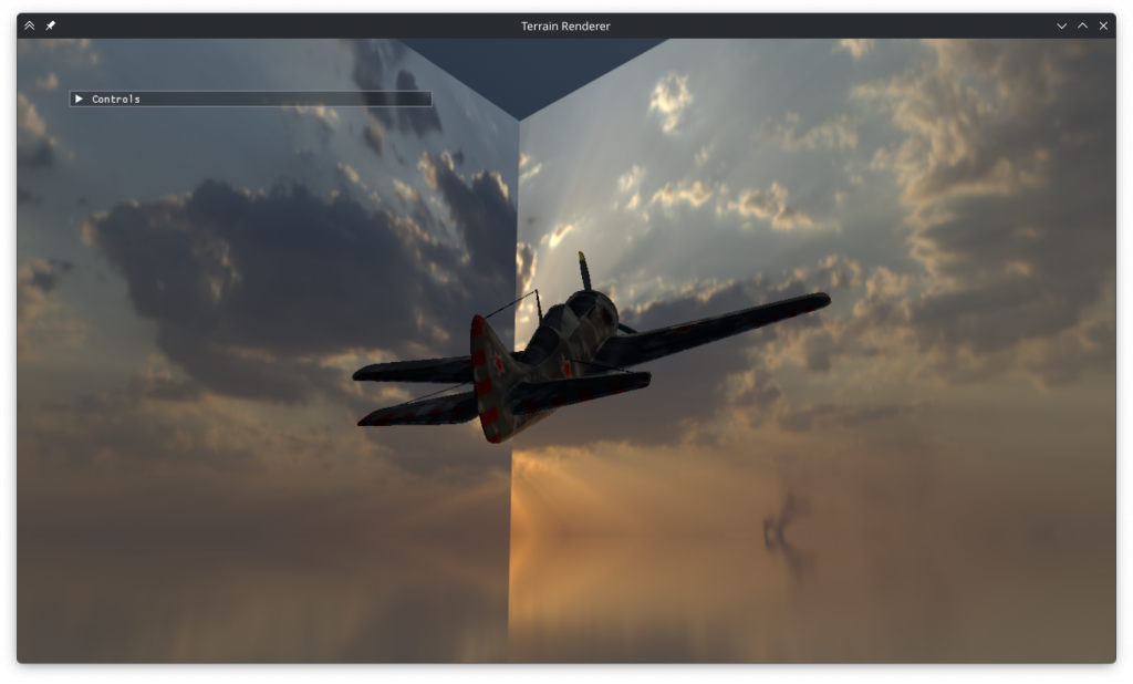
I tried displaying my old environment shaders using the cubemap as well. When rendered into a cube map, my second shader is discontinuous on all edges.
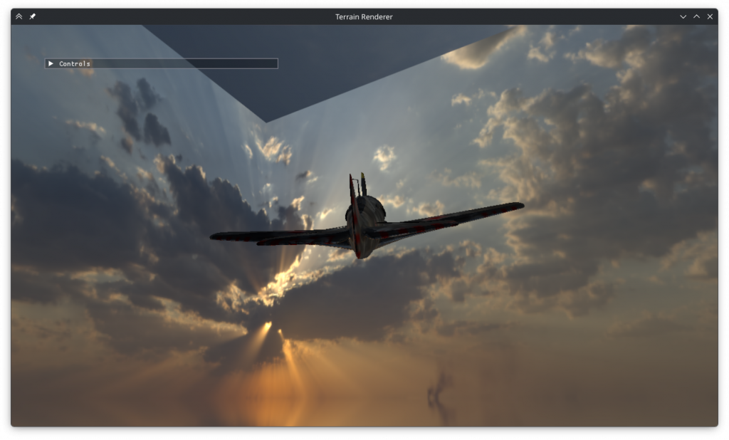
My first shader is surprisingly only discontinuous on the top and bottom.
Clouds
I moved on to implementing the clouds. I added a new clouds fragment shader that’s run in a second pass during the cubemap generation. Initially I tried using sine waves to generate the clouds like I did the water waves but this resulted in a fabric weave like look instead of clouds. So I implemented a Perlin noise based solution based on the course slides. I had some initial problems regarding negative coordinates and enabling alpha blending but eventually generated some semblence of clouds.
Next was picking the right parameters. To see the clouds easily I set the cloud color to dark grey. I ruled out using prime octaves as it caused overly smooth clouds and ruled out a second noise pattern as it didn’t improve the results. I tried adding a cloud height parameter that scaled down the cloud magnitude by its distance to a desired y value but I couldn’t make it work. Instead increasing the y frequency produced the flat looking clouds I desired.
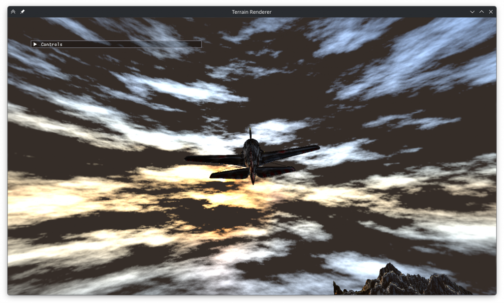
Trying different octave counts I found that higher numbers generally looked better but the differences became unnoticeable by 10. I wanted the clouds to have volume to them so I implemented the option to take multiple samples along the view direction. Just like the octave count I observed diminishing returns with sample counts above 10, but high values also caused haziness so I kept it at 6.
I found that octave scaling (the magnitude decrease rate of larger octaves) numbers between 0.3 and 0.7 produced the best results. Interestingly, the clouds generated by values below and above 0.45 seemed almost complementary in the areas of the space they filled. The values below 0.45 resulted in smooth, hazy clouds while values above 0.45 resulted in ragged clouds. I decided on a value of 0.47, best of both worlds.
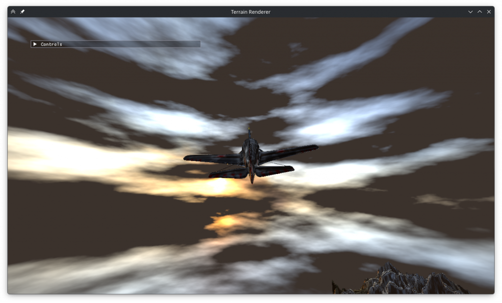
For sample scaling I observed that values below 0.5 caused the additional samples to make no difference while high scaling values caused a hazy look. I settled on 0.74.
I wanted the clouds to have more volume, so I added a field to TextureGL that holds the sun direction (calculated during import), and used that to cast sun rays. The sun rays work by casting a ray towards the sun from each sample and subtracting the sun ray cloudiness value from 1 to get illumintaion. This illumination is multiplied by the cloudiness at the sample position, scaled down by the cloudiness of earlier samples and added to the total brightness of the ray. Although I thought this was a good scheme I could not get the sun rays to produce the image I wanted. Instead of illuminating the sun-facing side of every cloud, this resulted in randomly shaped bright areas. It is possible that I made an error in the implementation, and it’s also possible that the system could have worked if I had added non linear scaling or early termination.
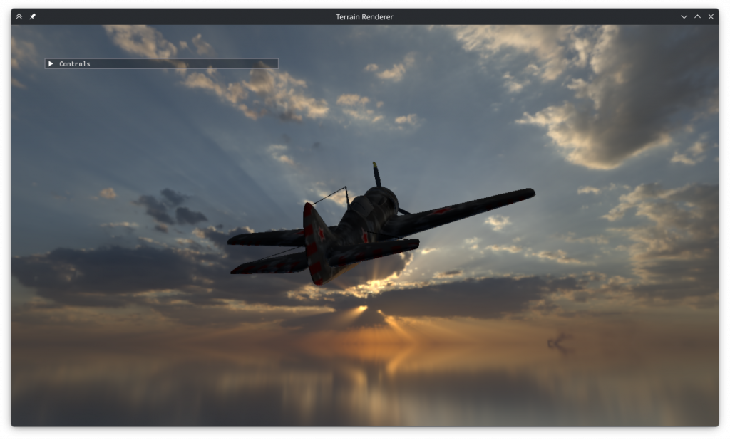
I tried to create an effect where the sun’s intense brightness punches through cloud cover with a halo effect but this was once again not successful.
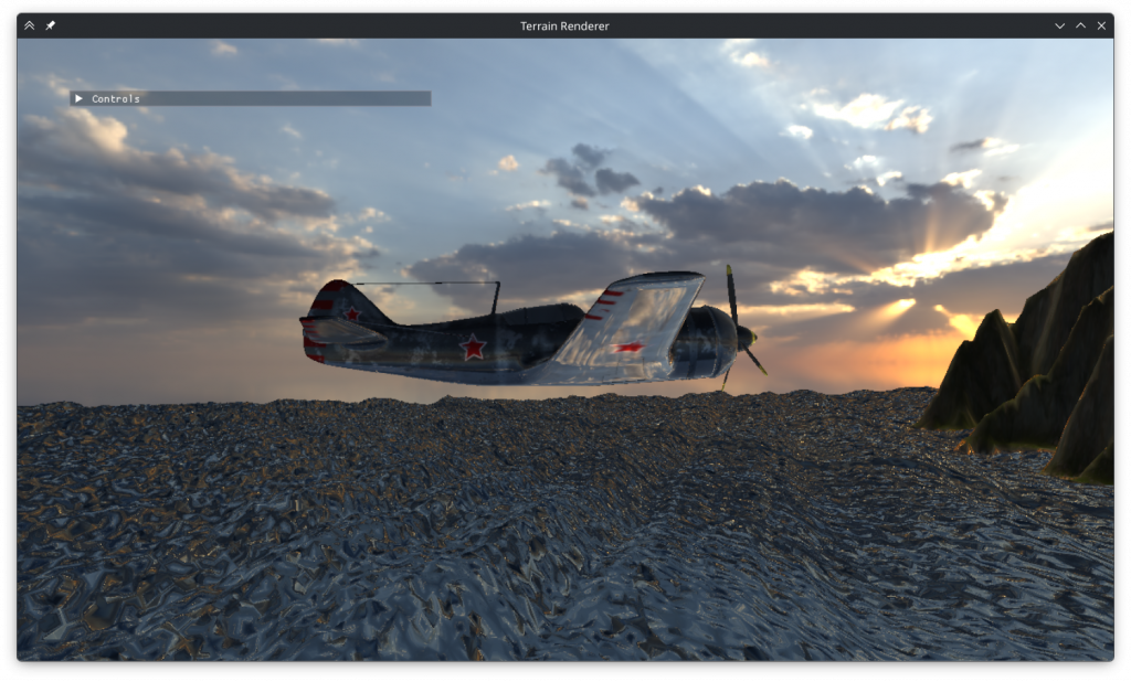
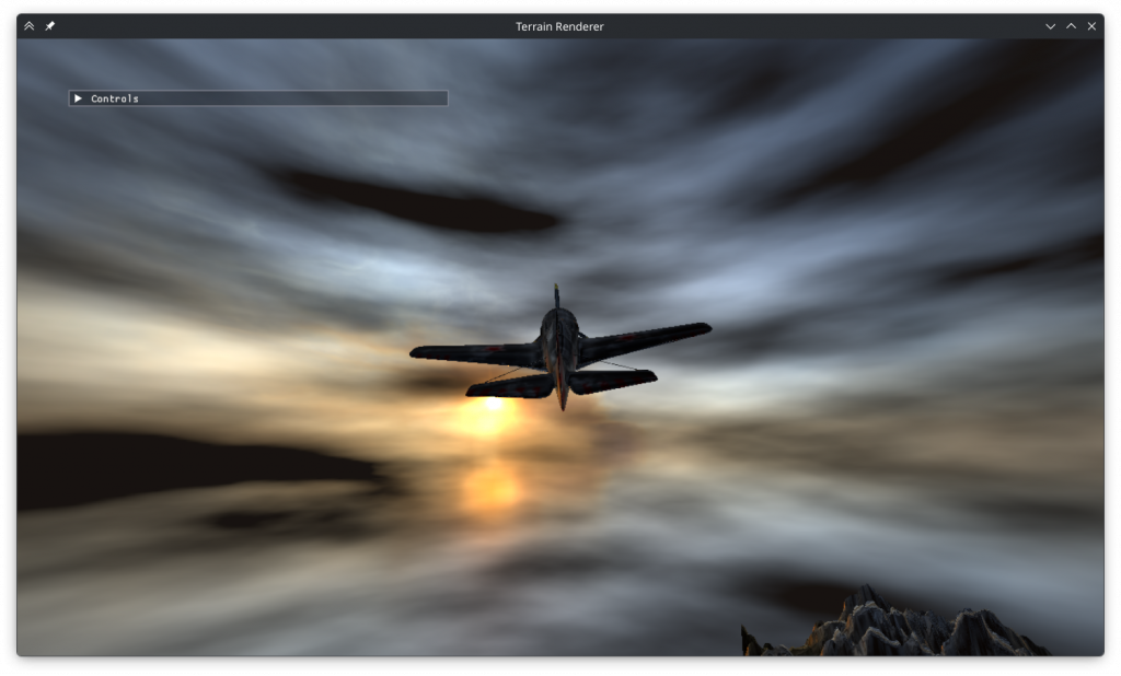
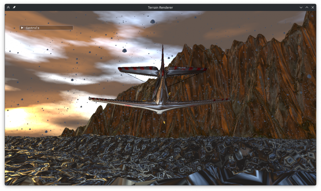
I decided to keep the dark clouds as I wasn’t sure how to color correct bright clouds and dark ones would make more sense as storm clouds. I decreased the target exposure to match the gloomy look I wanted and changed the illumination of the terrain to match the illumination of the plane. This made it look metallic but it was worth it to make the brightnesses match. I also added color to the sun illuminated areas, and that made it look like the sun was reflecting off the clouds.
Rain
My final task was adding rain. I created 4 new shaders for rain rendering: compute, vertex, geometry and fragment. To import the geometry shader I added it to the enum options of the ShaderGL struct. Remembering that compute shader isn’t a part of the graphics pipeline I created a ComputeGL struct that imports it in a standalone fashion. I included all the shaders and the texture in a Rain struct.
First shader I wrote was the compute shader. I created an ssbo, populated it with random particle positions and uploaded it to the gpu. Although its syntax was a bit confusing I eventually managed to add it to the compute shader as well. Unfortunately, I discovered that calling glUseProgram on the compute shader caused an error that stopped anything from getting displayed. I decided to fix this later so after writing the internals of the shader to handle movement, state change and respawning I commented it out.
The vertex shader to access the ssbo and pass on the vertex data was quick to write. The geometry shader was also simple and although it gave some compilation errors regarding default inputs and outputs those were also quick to fix. Finally I wrote the fragment shader to display the rain texture, scaling its x axis to 0.25 and shifting it by the state integer passed onto it all the way from the vertex shader. I tried rendering the raindrops without animating them with the compute shader, but I discovered that even that didn’t work. Having the geometry shader in the code at all was erroring out the program.
So it was time for the hard part: debugging. I began with the compute shader, debugging every step of its import process. After trying many random things I eventually discovered that it didn’t break the program if it was run as a part of the graphics pipeline via glUseProgramStages. The geometry shader didn’t budge to changing random things in the code. The way it errored out was also strange, as the error wasn’t happening immediately after it was used or after the draw call. I found via renderdoc that it remained in the pipeline after the rain pass was over and caused issues with other render passes. Unbinding it at the end of the pass fixed the problem.
Now I could get something to display, but the rain was nowhere to be found. So I got rid of the view / projection matrices, limited vertex coordinates to 0-1 and disabled texture mapping to get the pass to display anything. After fixing the order of the generated vertices a square finally showed up. And a square was all I got, the rest were missing. The cause was passing an ssbo pointer pointer to the glBufferData function instead of the pointer itself. Reverting the matrix changes, now I had a grand total of.. 8 squares out of the 11 I was trying to display, and 3 of them were at the wrong positions. Debugging this was also very difficult, but eventually I realized looking at renderdoc that the alignment of glm::vec3 and GLSL vec3 were different.
With everything working I increased the particle count, enabled the compute shader, enabled texture mapping and added the code to make the squares always face the camera in the x-z plane. The textures were too bright without shading so I multiplied the colors by 0.003. The rain was seemingly working, but something was wrong with the splash animation. It wasn’t triggering where it should and it was triggering where it shouldn’t. So I opened the program in renderdoc and found that the depth buffer was entirely white. I investigated the cause, but upon closer inspection the closest parts of the plane had depth values as low as 0.997, so not entirely white. Thinking that this was a depth precision issue I tried various schemes to make the drops not collide with the cubemap but all was to no avail. In the meantime I fixed some issues regarding perspective divide and ndc conversion. The problem turned out to be caused by reading from a renderbuffer as if it were a texture.
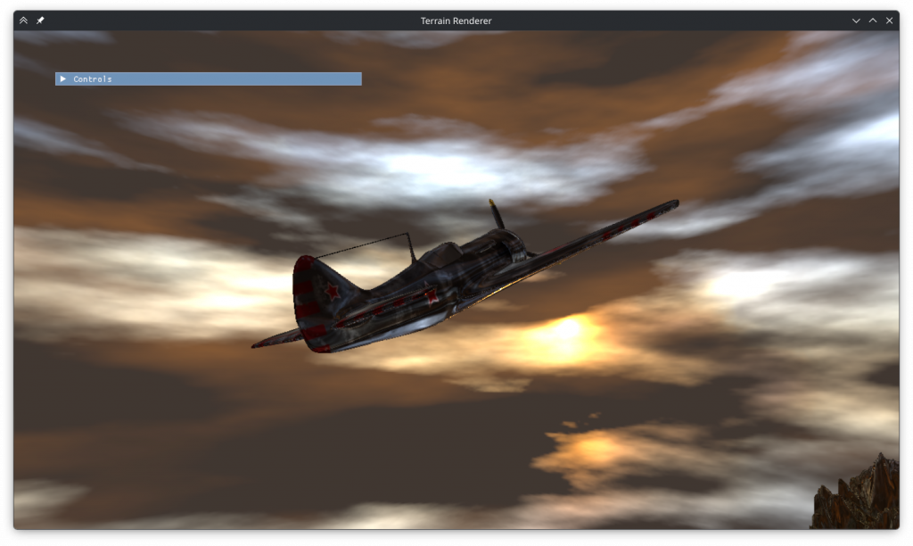
After fixing all the bugs and changing some of its parameters as well the rain looked good.
Performance
I wanted to test the program on my laptop’s iGPU to make sure there were no performance problems. To my horror this was what it looked like on it:
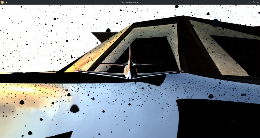
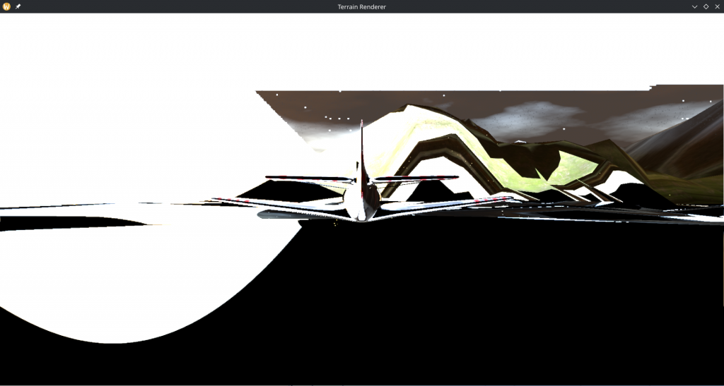
The cubemap looked like one of my early attempts at creating a cube model, and the reflections on the environment were moving around and shaking wildly. The imgui window was also missing.
I decreased the particle count and screen resolution, but what finally fixed it was decreasing the cubemap size. At 2048 it looked like above, at 1024 it looked a bit better and the imgui window text (but not the background) was visible. At 512 it looked right. I think the cubemaps above 6×512 caused vram allocation issues that silently returned black pixels instead of erroring or slowing down.
Conclusion
This was definitely a learning experience for me, not just for the graphics programming concepts but also for how OpenGL works and how to debug it.
Leave a Reply