Hi, this is my fourth and final blog post about Ceng 469, and it’s about my attempt at creating a holographic texture shader in OpenGL.
The Idea
The idea behind this project was to create a texture that, like real life holograms was contained in a 2D plane but created the illusion of 3D depth when viewed through different directions. With real life coherent light holograms this is done by reflecting a coherent light source off the object of interest and capturing the interference pattern on a film. When viewing the hologram under the same coherent light, the light that passes through the interference pattern interferes with itself to recreate the original light waves.
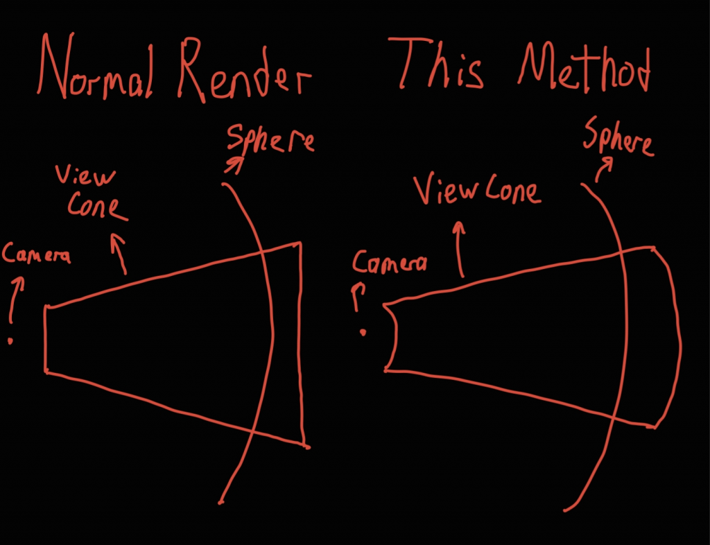
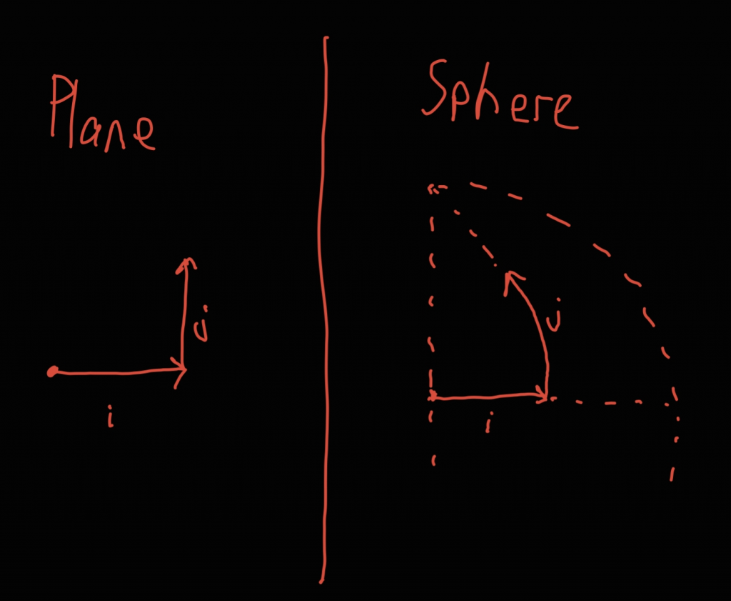
My idea on doing this digitally was to first pick a light wavelength, texture pixel size and texture resolution. While baking the texture, a quad of size pixelSize * resolution is imagined to be placed at the position and orientation of the camera. Then, for every pixel of the texture the object is rendered from the position of that pixel on the quad. This render is controlled by separate parameters sample count (resolution) and fov. At the end of the fragment shader, the color value is multiplied by the encoding term, which is abs(sin(fragmentDistance * 1 / wavelength)). Finally, the image is mipmapped down to 1 pixel and copied to the final texture’s pixel.

To display the resulting texture, it would be mapped onto a quad of the same size. Then for every fragment, multiple samples would be taken around the fragment center, and once again the color values would be multiplied by the encoding term of the sample position and summed. In real life the sample area is controlled by the aperture of the camera, but in the shader this would once again be a parameter.
GLTF
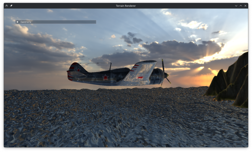
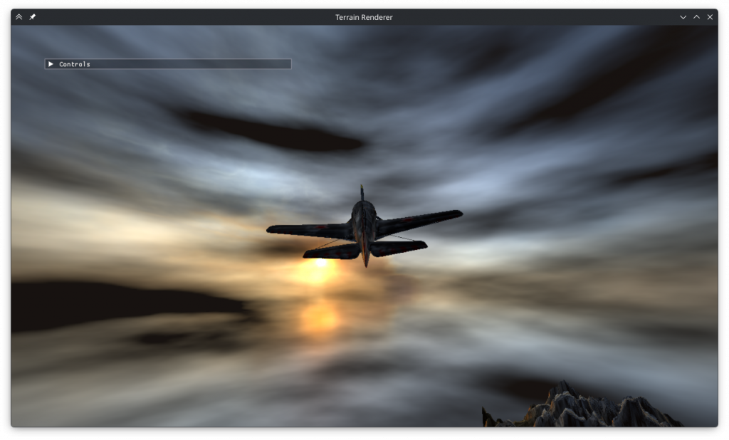
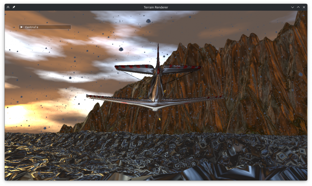
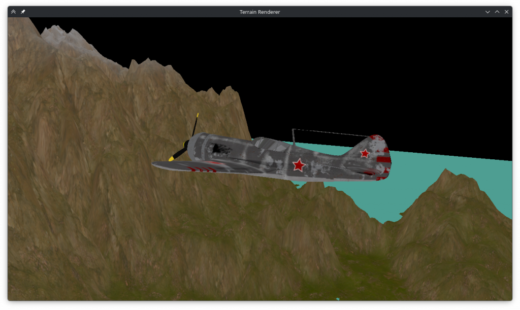
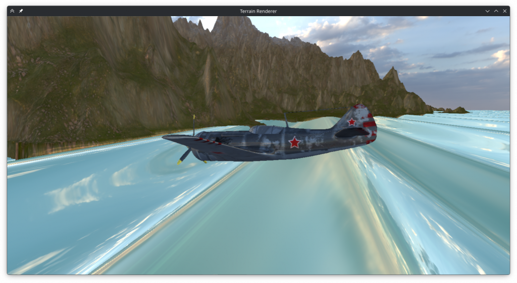
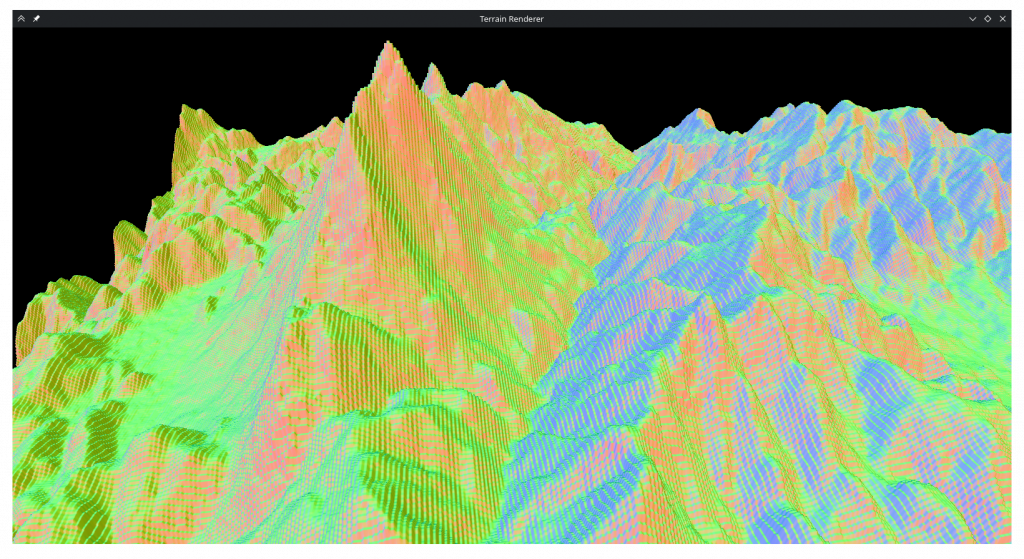
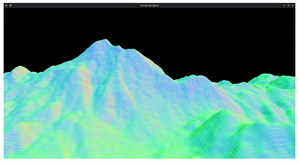
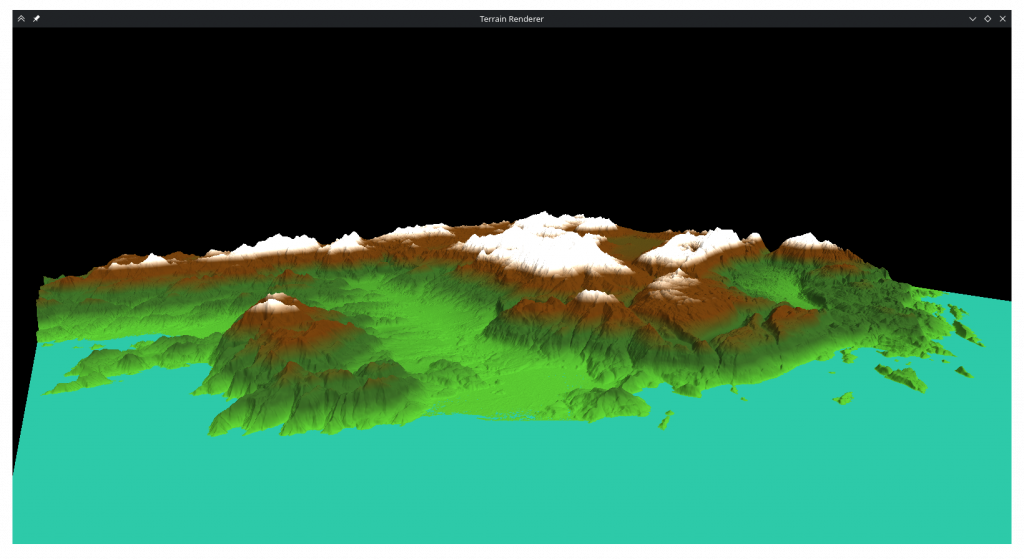
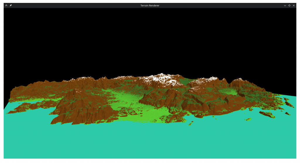
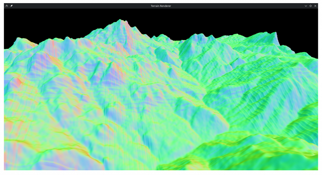
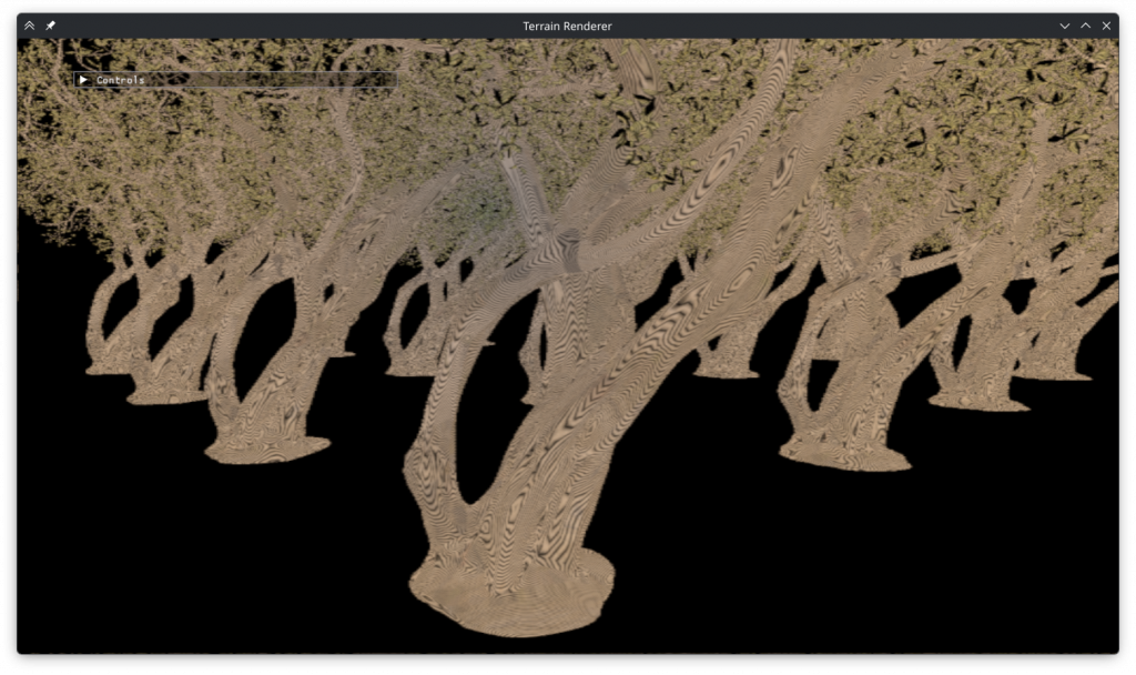
I began with something somewhat tangential to the goal of making a hologram: writing a GLTF importer. I wanted to show the program displaying a complex model and I was growing tired of the tessellated terrain of the previous homeworks, so I opened polyhaven and looked for models with large triangle counts. I found a tree model with 2 million triangles. Seeing that polyhaven doesn’t have .obj files I can download, I asked an LLM what was the easiest format to work with and learned that it was GLTF. After messing around a bit with Assimp I decided it was too complex for my project and turned to tiny_gltf.
tiny_gltf is a header-only library for gltf parsing. I had kind of assumed it would have first class support for importing them to OpenGL and have good documentation but this turned out to not be the case. When I opened the Github repository of tiny_gltf, I saw a notice that tiny_gltf 2 (cpp) was depracated last year and there was a new tiny_gltf 3 (c). I tried using the new version until I realized that not only did it not have first class support for OpenGL, but also didn’t have any code examples or documentation. I switched to tiny_gltf 2, which also didn’t have documentation but at least had code examples. The code turned out to only work for a specific GLTF file, but eventually I found the Khronos GLTF cheat sheet and learnopengl.com’s pbr articles and wrote an adequate importer based on it. It still has some issues (like incorrect texture mapping) but I decided not to spend more time on it.
In this process I also deleted and refactored parts of the hw3 codebase as it was getting too complex.
Hologram Baker
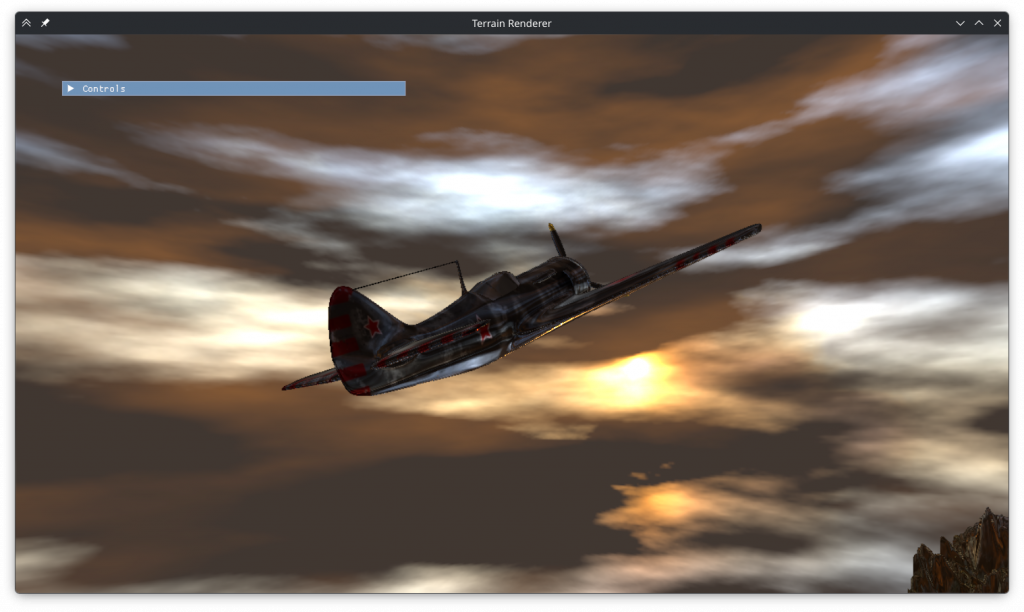
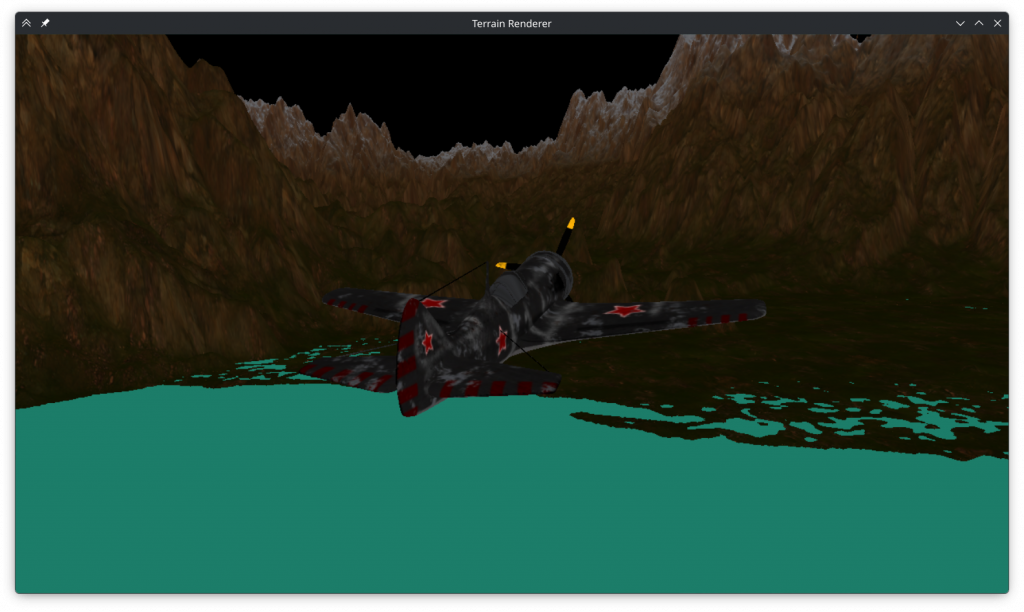
Next I wrote the class for baking holograms. It sets up an intermediary framebuffer that’s used for rendering the scene with sine encoding from each pixel’s perspective. At the end of the render, the color texture is mip mapped and the smallest mip is copied over to the corresponding pixel of the target texture. This happens before the drawing of the actual frame in the background.
For the distance encoding, I tried two methods: directly calculating the fragment distance in the fragment shader that renders the object, and doing it in a second pass by using the depth value of the fragment as distance. However as rotating the camera changes the depth value of points (while the distance is only supposed to be based on positions) the second method didn’t produce correct results.
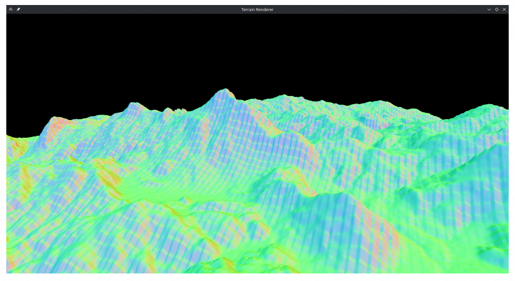
I faced some pitfalls when implementing the baker, like deleted move constructors or having to mipmap the target texture before writing to it, but it eventually produced a texture:

Hologram Displayer (aka, When it Went Wrong)
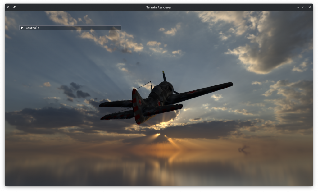
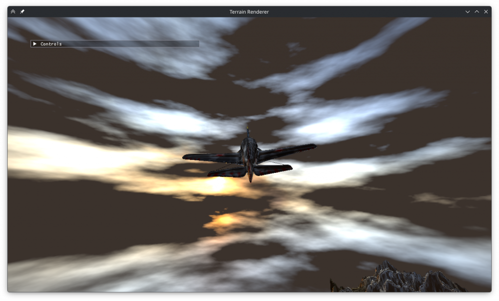
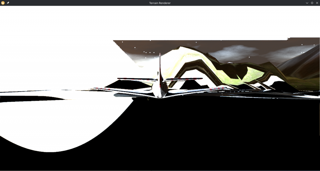
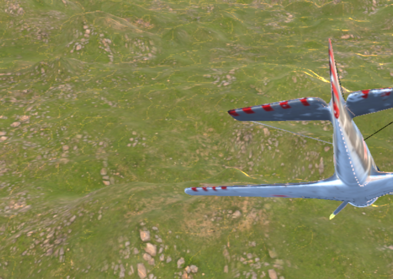
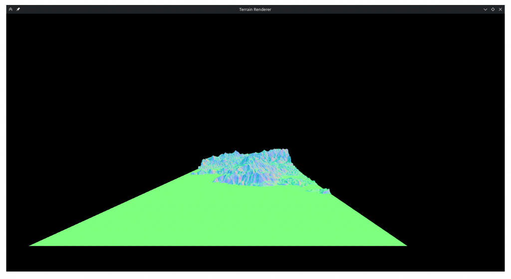
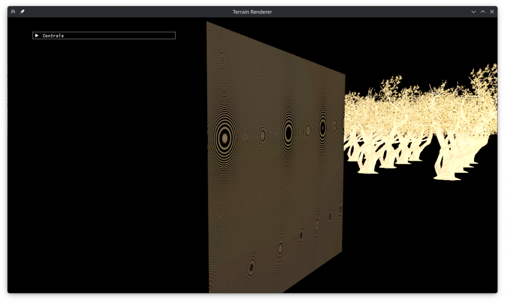
Without a way to display it, the texture doesn’t look like anything. The displayer draws a quad with the same dimensions as the baking surface, maps the texture to it and runs a fragment shader on it that once again multiplies the color values by the encoding term.
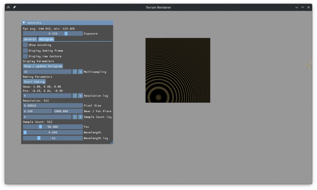
The result looked as above, no hologram. That was disappointing to see, but in hindsight there are multiple obvious issues with it.
The first issue is that the rate of change of the encoding term is visibly too small around the area of the quad where its plane is the closest to the camera. The hologram only has a chance of working if each pixel of the resulting image receives information from multiple pixels of the texture. With such an encoding, that information, even if it exists in the texture, isn’t decoded.
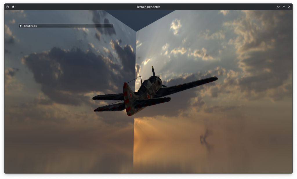
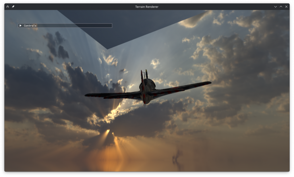
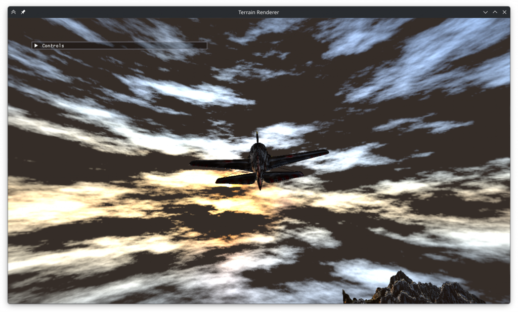
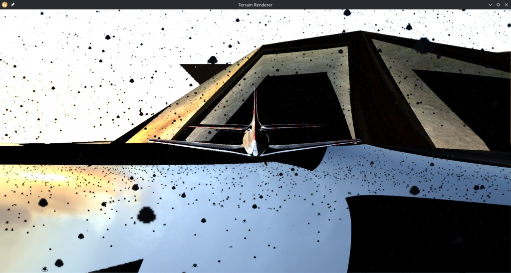
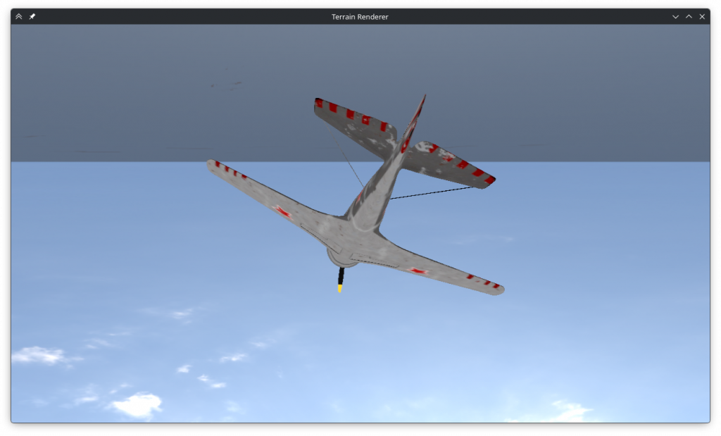
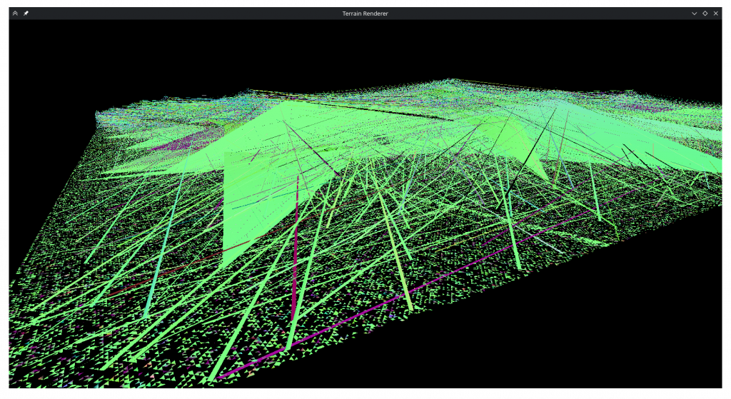
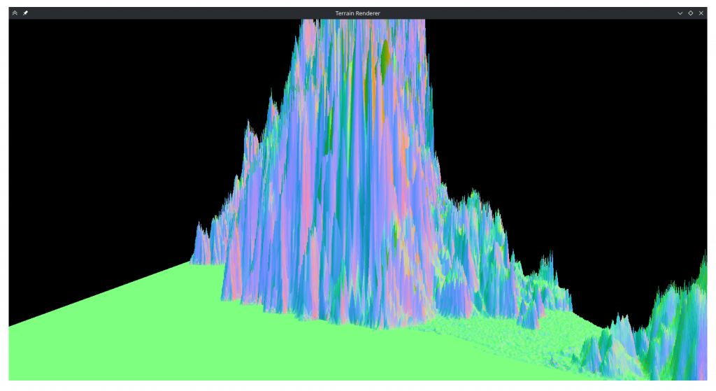
The second issue is visible above but is better demonstrated by this image:
In the areas where the rate of change isn’t too small, the high frequency causes extreme aliasing. Every pattern visible on the above image is an aliasing artifact, and this is with 32x multisampling. I’ve also tried a naive fragment shader for-loop based approach but it also wasn’t successful.
At this point I was tired (and I was out of time due to personal reasons), so I decided to stop trying. Initially I had thought if this didn’t work I could instead implement a real life hologram renderer based on published papers but I’m doubtful that can be done in the remaining time.
I added options for saving and loading holograms to the ImGUI to prepare the program for submission.
Reasons Why It Might’ve Not Worked
- My understanding of the theory might be wrong. This might be too simplified compared to how real life holograms work.
- An actual light source position might be necessary for encoding, instead of treating the light as being emanated from the rendered object.
- Saving the light’s angle in the texture in addition to its amplitude could be useful.
- This implementation might be too coarse compared to real life.
- In real life the wavelength of visible light is ~5×10⁻⁷m. The ‘pixel size’ of holographic film is even smaller. In this project I worked with a wavelength of at least 1.2×10⁻⁴m.
- To make the wavelength smaller, the pixel size of the hologram needs to decrease to prevent aliasing. The maximum texture size reported on my computer is 32k, which would mean, with the <0.0000003m pixels necessary for a real life wavelength, the size of the hologram quad would be about 10cm.
- The sample count also possibly needs to increase with smaller wavelengths. At the smallest wavelength I used the intermediary was already a 8k texture, only 4x smaller than the maximum possible.
- I’m not sure how many samples would be necessary for the hologram to work with a real life wavelength, but it’s possible that the number is so large that it won’t work or won’t work in real time with an implementation I can write.
- The hologram baking times seems to increase by 4-8x per halving of the wavelength. Even if everything else worked, using it to bake a taxing scene would be an unreasonable endeavor.
- Saving the image as .png might’ve quantized it too much.
Conclusion
Using holographic techniques in OpenGL is not viable, if not for my inability to implement them, at least for the astronomical increase in baking times.
I’m not sure how computer generated holograms are made, but now I understand why a paper I read had called it a bandwidth challenge.
The part I enjoyed the most was refactoring the rendering code into generic objects that can be used with different models / shaders etc, even if I didn’t get to use it.