Monthly Archives: November 2025

BVH Implementation for Ray Tracer

For the second homework of my CENG 795: Advanced Ray Tracing course, I tried to expand my previous ray tracer by adding its missing features from the previous homework, adding an acceleration structure (specifically a BVH with median split method), and modifying the parsing and tracing to support mesh instances and transformations. Most of these attempts failed unfortunately. Nevertheless, I will be explaining every step of my implementation and providing some rendered images from my attempts below.

Wrapping the Tracing Process and Re-attempt at Refraction

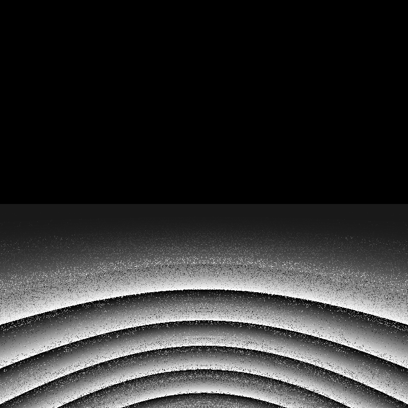
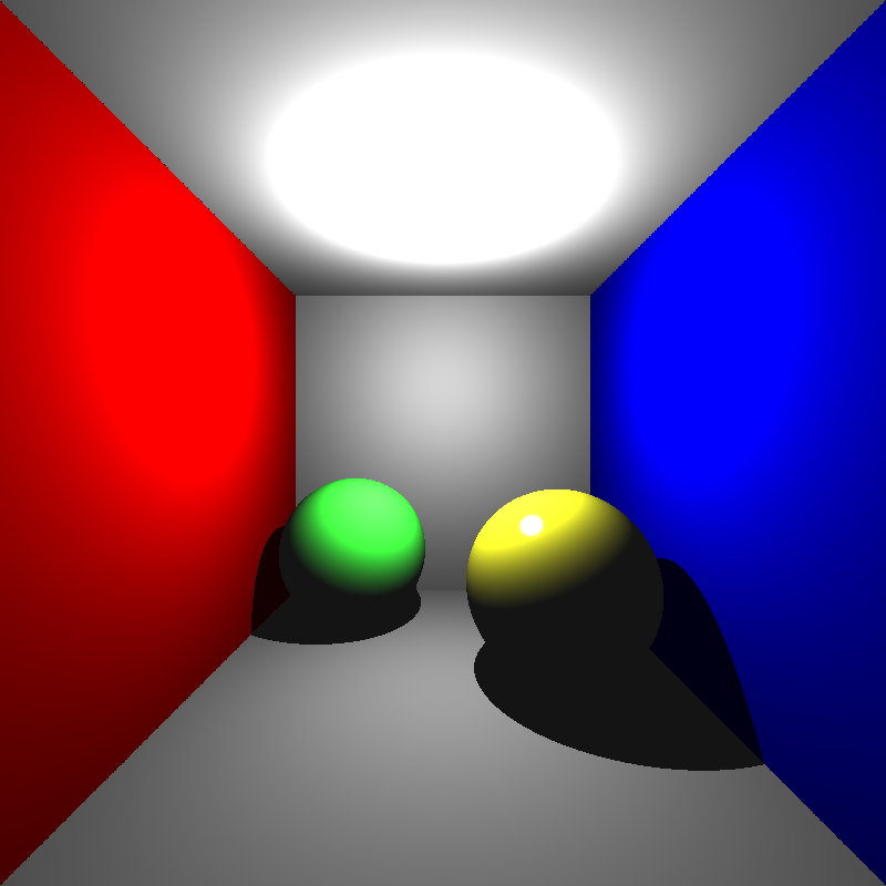
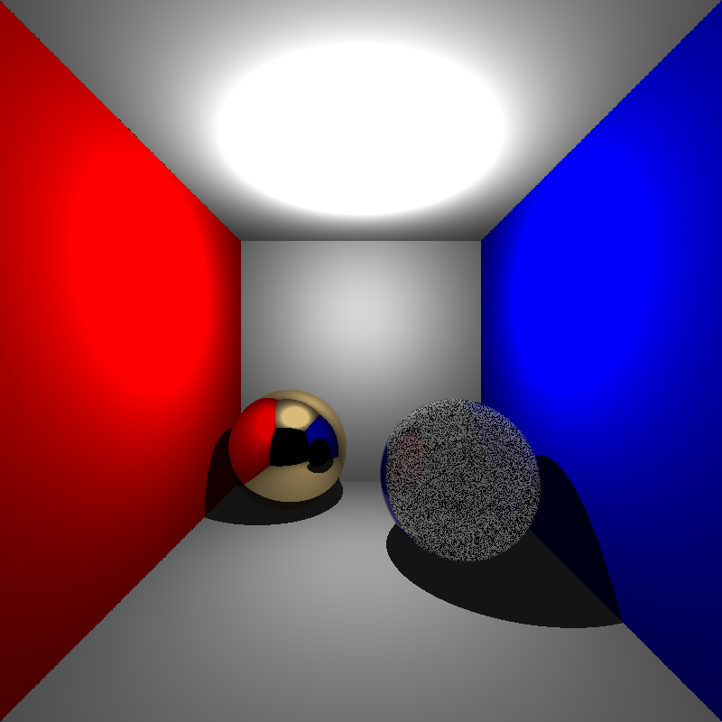
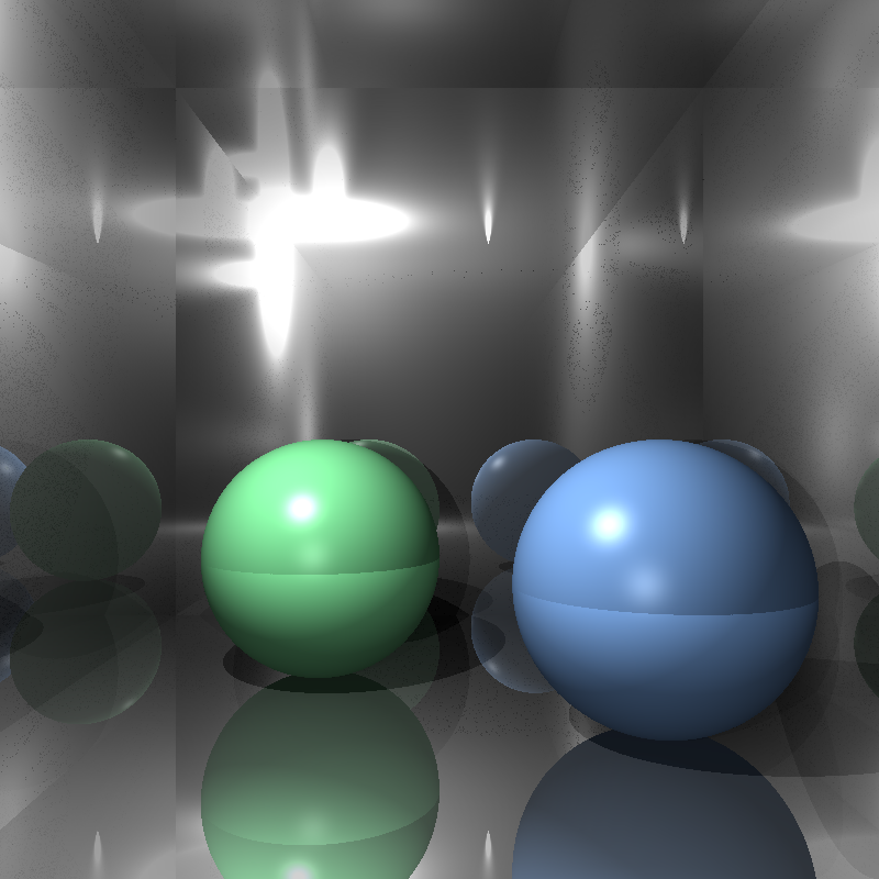
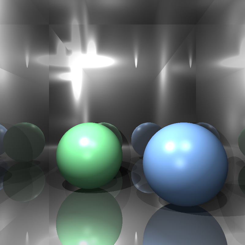
Before I began implementing the required features of this homework, I believed that I needed to move my tracing functions into a single trace function so that calculating hit detection during BVH traversal would be easier and I could perhaps fix my refraction calculation during this process. I wrapped the tracing process in a single function called trace() that recursively calls for itself when it detects reflection or refraction. The calculations for intersection, color, shadow, and reflection are essentially the same before, but I rewrote my refraction calculation. My refraction calculation now supported multiple reflection and refraction iterations instead of one, and the reflection and refraction weights are clamped in case one of them exceeded 1. The images below are renderings of cornellbox_recursive.json; the top image is rendered by my previous ray tracer, and the bottom image is rendered by my modified ray tracer:

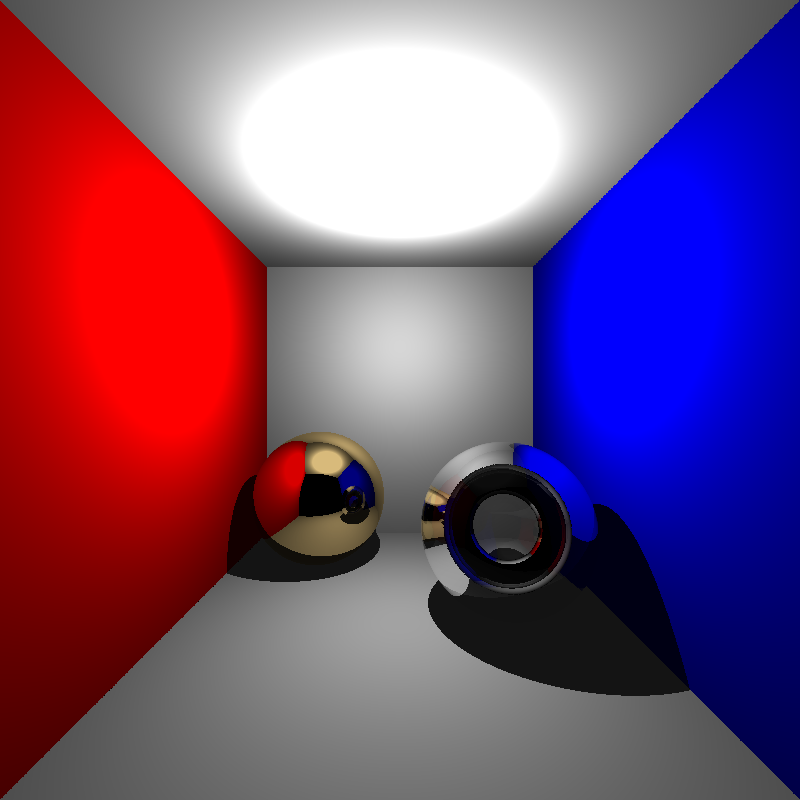
While the dielectric sphere is rendered a lot better (at least parts of the background are visible now) the refractions were still very off. This result was still not quite acceptable, but I did not want to waste too much time on details that were irrelevant to this homework, so I moved on with my implementation.

Applying Transformations

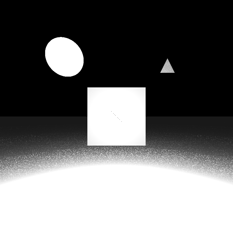
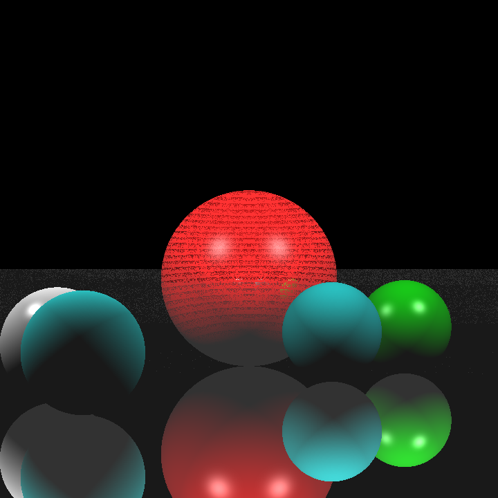
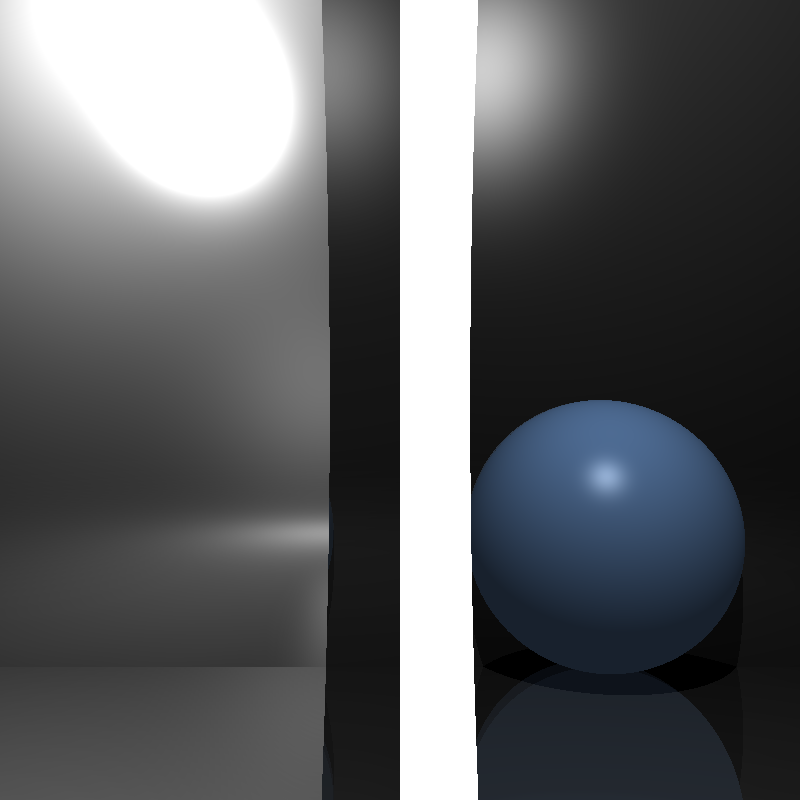
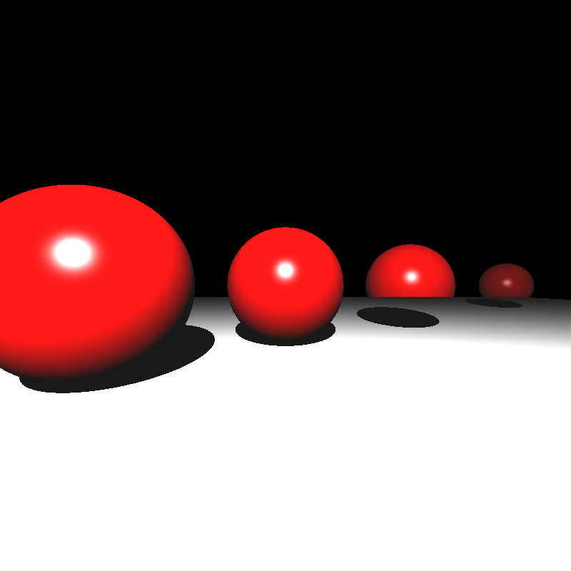
To apply transformations to objects, I decided to store the composite transformations for the object vertices and their inverse transposes for their normals initially. Then I would apply the transformations on each vertex and normal before rendering and calculate intersections through world space. After spending a little time implementing and fixing some minor bugs, this implementation seemed to have worked, at least for simple scenes. But I noticed a problem for spheres that had non-uniform scaling transformations. Below is a rendering of spheres.json when I tried to apply the transformations to the objects:

spheres.json with transformations applied to objects

This result was quite perplexing. The process of calculating the composite transformations and applying them should have been incredibly simple. After going over my implementation, I couldn’t really find any problems either (But there actually was a major problem that I overlooked, much to my dismay. I’ll talk about the problem toward the end of this section). Then I realised something. The radii of the spheres never got transformed. As no multiplication operations could be done on them, the radii would not change and the spheres would still appear as uniform spheres instead of ellipsoids. While I could have multiplied the radius by the common diagonal value for uniform scalings, this would not have worked for non-uniform scalings.

While searching the internet over this issue, I found these posts that had interesting ideas:

https://stackoverflow.com/questions/34220370/apply-matrix-transformation-to-a-sphere

https://math.stackexchange.com/questions/3159618/principal-axes-of-deformed-ellipsoid

Transforming the sphere into an ellipsoid with different principal axes sounded interesting, but it felt like trying to implement something like this would have put too much unnecessary work, so I decided to apply the inverse of the transformation on the ray position and direction for each object and calculate that way.

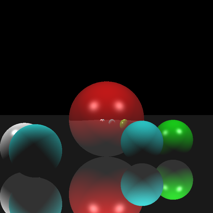
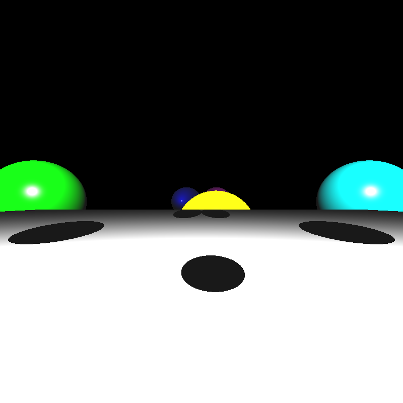
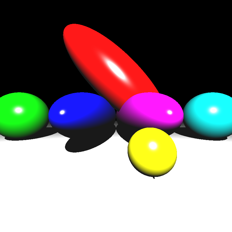
When I finished implementing it, I got the results below:

spheres.json with incorrect intersection
ellipsoids.json with incorrect intersection

The reason for this was incorrect intersection calculation, which was caused by several minor mistakes like using local t values to compare instead of t values for world space and setting the w component of directions (such as ray direction and normal) to 1 instead of 0. Fixing these issues still gave me incorrect results:

spheres.json
mirror_room.json
ellipsoids.json

Still oddly incorrect results yet I was sure there were no errors in my implementation. After spending a considerable amount of time contemplating over this, I finally found the major problem I mentioned before. The problem was in the order of matrix multiplication. When calculating the composite transformations I put the matrices in incorrect order. The amount of small yet crucial details I managed to overlook is honestly astonishing. I doubt anyone could match me when it comes to that.

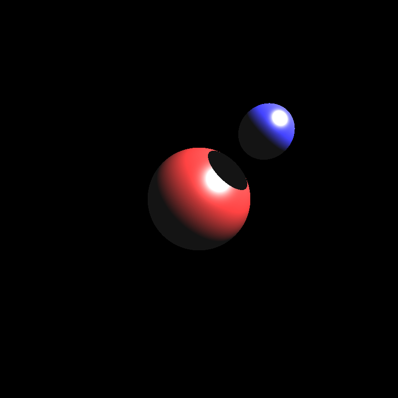
With the transformation ordering now fixed, I got the results below:

spheres.json
mirror_room.json
ellipsoid.json

Somehow the results were still incorrect, but I had had my fill of transformations at this point, so I decided to move onto implementing the BVH.

Implementing BVH, Mesh Instances, and PLY Parsing

I normally intended to explain mesh instances and ply parsing in another section, but I could not implement them in time, so I decided to explain them in this section. This entire section is actually more about my shortcomings as even my BVH implementation seems to be almost useless.

For my BVH implementation I tried to implement a two-level, linear BVH tree with median splitting where each mesh would have its own bottom level BVH tree. For this, I wrote a small bounding box struct that just held the minimum corner, maximum corner, and its center. I then wrote a primitive struct that would represent each object and stored these primitives in the array. Each BVH node would keep track of its primitives by primIndex and primCount. In the BVH tree itself, each node’s left child is in the next index of the parent and the right child is offset by rightOffset. Below is a simplified version of these structs:

struct BBox {
    parser::Vec3f min_corner; // minimum x, y, z of the box
    parser::Vec3f max_corner; // maximum x, y, z of the box
    parser::Vec3f center;

    BBox() {
        min_corner = {0.0, 0.0, 0.0};
        max_corner = {0.0, 0.0, 0.0};
        center  ={0.0, 0.0, 0.0};
    }

    BBox(parser::Vec3f min_vec, parser::Vec3f max_vec, parser::Vec3f center_vec) {
        min_corner = min_vec;
        max_corner = max_vec;
        center = center_vec;
    }
};
struct BVHNode {
    BBox bbox;
    uint32_t firstPrim;     // index in primitives[]
    uint16_t primCount;     // leaf count
    uint16_t rightOffset;   // index offset to right child
    uint8_t  nodeType;      // 0=leaf, 1=interior
};
struct Primitive {
    BBox bbox;
    enum { SPHERE, TRIANGLE, MESH_TRI, MESH_TOP } type;

    parser::Sphere sphere;
    parser::Triangle tri;

    parser::Mesh mesh; // only valid for MESH_TOP
    std::vector<Primitive> meshFaces; // for per-mesh BVH
    std::vector<BVHNode> meshBVH;

    parser::Matrix4f inverse_transform;

    Primitive(parser::Sphere s);

    Primitive(parser::Triangle t);

    Primitive(parser::Mesh m);
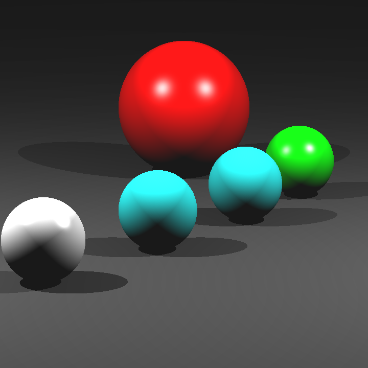
};

My structs probably could have been more efficient, but my initial priority was to get a working BVH. I built a BVH recursively and assigned primitives to each split by which side they are on compared to the median of the given bounding box. When I ran my ray tracer on some simple scenes, I got the results below:

mirror_room.json
ellipsoids.json

Oddly enough, these scenes were now being rendered properly. I couldn’t figure out the reason behind this, but probably there was still something wrong with my intersection calculation.

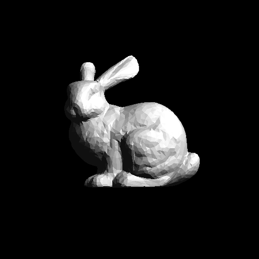
Unfortunately, I couldn’t implement a parser for PLY files. I tried to use the ply library by Paul Bourke, but I could not get it to work no matter what I did. I also tried to get Google Gemini to produce a parser for me (it was the only model working when Cloudflare was down), but its implementation didn’t work either. For mesh instances, the ones in the example files all referenced PLY meshes as their base meshes, so I couldn’t really get around to implementing that. It felt like it would be pointless if the base meshes did not exist. I didn’t give a table for render time either because the simple scenes that could be rendered take a second at most and I don’t have render times for complex scenes that use PLY files.

In the end, this homework turned out to be less about producing a flawless ray tracer and more about discovering just how many ways I can break one. I was quite impressed by the amount of mistakes I’ve made. In any case, I’ve come to understand the importance of writing modular and maintainable code that can be extended as needed for future use.

Simple Ray Tracer in C++

For the first homework of my CENG 795: Advanced Ray Tracing course, I implemented a simple ray tracer in C++ that reads scene data from a JSON file and renders images using basic ray tracing methods. My ray tracer performs ambient, diffuse, and specular shading calculations for intersected objects, as well as shadow calculations when the light source is obstructed by another object. Additionally, it performs reflection calculations for mirror, conductor, and dielectric objects, and unfortunately, it incorrectly calculates refraction for dielectric objects. In this post I will explain my implementation process, the errors I came across, and the resulting images with their rendering time. I will also provide some explanations that might be redundant. This is totally for the sake of future visitors who might not be familiar with ray tracing and absolutely not to increase the length of this post.


Parsing and Storing the Scene Data

According to the homework specifications, I was required to parse both JSON and PLY files for scene data. I used Niels Lohmann’s JSON library to parse the scene information and stored it using a set of custom structs. Unfortunately, I wasn’t able to implement PLY parsing in time, so my ray tracer currently only works with JSON files.

All scene-related data is contained within a single Scene struct, which includes several other structs corresponding to each field in the JSON file. While the homework document already explains each field, I’ll briefly summarize them here for completeness.

Below is the Scene struct and a brief description of each field:

 
struct Scene
    {
        //Data
        Vec3i background_color;
        float shadow_ray_epsilon;
        float intersection_test_epsilon;
        int max_recursion_depth;
        std::vector<Camera> cameras;
        Vec3f ambient_light;
        std::vector<PointLight> point_lights;
        std::vector<Material> materials;
        std::vector<Vec3f> vertex_data;
        std::vector<Mesh> meshes;
        std::vector<Triangle> triangles;
        std::vector<Sphere> spheres;
        std::vector<Plane> planes;
        //Functions
        void loadFromJSON(std::string filepath);
    };
  • background_color: A vector of integers containing the RGB value of the scene background.
  • shadow_ray_epsilon:  A small float value used to offset the intersection points in order to prevent self-intersection.
  • intersection_test_epsilon: A small float value that was unspecified in the homework documentation. I initially assumed it was supposed to be used to offset the intersection points while calculating reflections. This has caused quite a bit of headache for me while implementing reflection calculation.
  • max_recursion_depth: The maximum amount of times a ray’s bounce will be calculated when reflected.
  • cameras: An array of Camera objects, each containing information about the camera vectors and the image plane.
  • ambient_light: A vector of floats defining how much light an object receives even in shadow.
  • point_lights: An array of PointLight objects, each containing a vector of floats for position and a vector of floats for intensity.
  • materials: An array of Material objects, each containing the type of material and the necessary values for shading.
  • vertex_data: An array of float vectors, each containing the position of the vertex in the given index.
  • meshes: An array of mesh objects, each containing the shading type, the index of the material, and an array of Face objects.
  • triangles: An array of Triangle objects, each containing the indices of its vertices, the index of its material, and a float vector representing its normal.
  • spheres: An array of Sphere objects, each containing the index of its material, the index of its center vertex, and its radius.
  • planes: An array of Plane objects, each containing the index of its material, the index of its point vertex, and a float vector representing its normal.
  • loadFromJSON: The function to parse and store the scene data.

Ray Calculation and Object Intersection

To give a bare bones explanation, ray tracing works by tracing a ray for each pixel of an image, checking for any objects intersected along that ray, and calculating the corresponding color based on the material and lighting. My ray tracer is just as bare bones as this explanation, it simply calculates a ray direction for each pixel, checks if any object is intersected, and computes the shading of the object at that point. Despite these simple steps, I made a lot of mistakes in my initial implementation. I’ll first show the results of some minor ones. The images below are all rendered from simple.json:

Result of casting the horizontal and vertical steps to int instead of float

Result of setting an incorrect minimum t after fixing the horizontal and vertical steps

Result of overflowing color values at certain pixels after fixing the minimum t value

Result of minor mistakes in intersection functions after fixing the overflow issue

Result of incorrect half vector calculations for specular shading after correcting the intersection functions

Result of fixing the half vector calculation

The image above is the correct rendering of simple.json. When I finally obtained the image above I thought that the base of my ray tracer was now complete. However, when I ran the ray tracer on other sample scenes, I got completely black images. This scene was the only one that was being rendered correctly. Debugging this problem took quite a bit of time.

My first thought was to check if there was something wrong with my intersection functions as no intersection occured at any pixel. I went over my implementations several times, I rewrote the triangle intersection function with matrix structs to make it more readable, I tested them with my own sample values. There was no issue with them.

My second thought was to check if there was something wrong with my calculations for the camera vectors and the image plane. I went over my gaze calculations for cameras with “lookAt” types, checked the corner calculations for the first pixel, yet nothing seemed to be wrong. Since the calculations for the image plane were correct the ray directions should have been correct by extension, or so I thought.

When I checked the ray directions individually while rendering, they turned out to be way off in some scenes. At this point I finally realised the issue: after calculating the pixel position I never subtracted the camera position from it, which gave me a position vector of the pixel instead of the ray direction vector. Since the camera of the simple.json scene was located at (0, 0, 0), the image was rendered correctly, while all the other scenes-which had cameras at different positions-appeared completely black. Fixing this mistake gave me the results below:

Rendering of spheres.json scene

Rendering of two_spheres.json scene

Rendering of cornellbox.json scene

Rendering of bunny.json scene

Reflection and Refraction Calculations

Next came the task of calculating the reflections and refractions for mirrors, conductors, and dielectrics. I initially just focused on implementing reflections for mirrors to make sure that I got the reflections working correctly first. The image below is rendered from spheres_mirror.json after I finished my initial mirror implementation:

First rendering of spheres_mirror.json

The result was a little off putting. The reflections of the center sphere even looked a little like a creepy, smiling clown. I believe the main reason for this was because I calculated the reflection rays incorrecty, but I wasn’t too sure as my initial implementation was quite messy. So I decided to redo the mirror implementation from scratch in a clearer way. My second mirror implementation gave the result below:

Second rendering of spheres_mirror.json

The result was a lot better than the first one, but there were still some noisy pixels scattered in certain areas. Tracking down the cause of this issue took a very long time, I almost decided to just move on and leave it as it was. I went over everything several times, but I couldn’t find anything wrong with my implementation. I redid the mirror implementation, but it still gave me the same result.
Eventually, I decided to tinker with the values inside the scene file. I tried changing almost every value inside the scene file without success until I finally decided to change the epsilon value. It turned out that the intersection_test_epsilon value-which was the value I used to offset the intersection point-was far too small and still caused self-intersection at certain points. When I used shadow_ray_epsilon instead, I got the result below:

Third rendering of spheres_mirror.json

At last, my mirror implementation seemed to be working correctly. After that, implementing Fresnel reflections for dielectrics and conductors didn’t take much time at all.
Now it was time for the final hurdle: calculating refractions. At this point I had very little time left so I decided to just implement a single refraction ray that did not bounce after leaving the object, yet even that proved challenging. Once again, the issue was noisy values at certain points but this time I could not come up with a solution. No matter how I changed the offset values or redid the refraction implementation, the result remained the same. Below is the rendering of cornellbox_recursive.json which contains a single conductor sphere to the left and a single dielectric sphere to the right:

Rendering of cornellbox_recursive.json

Finally, here are the rendering times for various scenes:

SceneRender Time
simple.json1 second
spheres.json1.35 second
spheres_with_plane.json1 second
spheres_mirror.json1.36 second
two_spheres.json0.2 second
cornellbox.json3.9 seconds
cornellbox_recursive.json4.7 seconds
bunny.json312 seconds
chinese_dragon>12hrs

Despite a few issues along the way, I learned a lot through this assignment. The mistakes I made were simple but taught me valuable lessons about the fundamentals of ray tracing. I’m excited to keep improving my renderer and explore more advanced techniques in the future.