Welcome to my blog page. For my first assignment in the Computer Graphics 2 course, I implemented the Catmull-Clark Subdivision Surface algorithm, and in this post, I will be explaining my process of implementing this algorithm and the errors I encountered along the way.
To understand how the algorithm worked, I first tried to go over the paper “Recursively generated B-spline surfaces on arbitrary topology meshes” by E. Catmull and J. Clark, and the algorithm’s Wikipedia page. I also found a video that gives a simple step-by-step explanation of the algorithm, which helped clear up some parts I didn’t quite understand in the first two sources I mentioned. You can access the video through the following link: https://youtu.be/mfp1Z1mBClc?si=3LienRGDQvvMI0ht
Once I had a clear understanding of the algorithm, I started on my implementation. My initial thought was that it would be better to first write the algorithm itself. Once that was done, I could take care of the rest of the specifications given in the homework document (which was a mistake in hindsight), so I started writing a function on the sample code provided by the assistants.
Throughout writing my implementation, the main problem has always been calculating the vertex normals properly. Once my first implementation was done, I added an octahedron object and tested it. Below is the output:
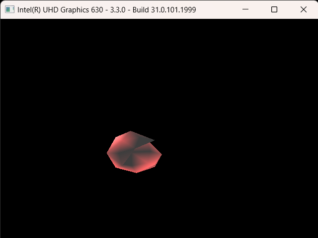
The reason my output was like this was I believe because I forgot to add the newly calculated faces, but I’m not too certain. It was a minor mistake I had made and I fixed it relatively quickly. The main issues started after I fixed this issue.
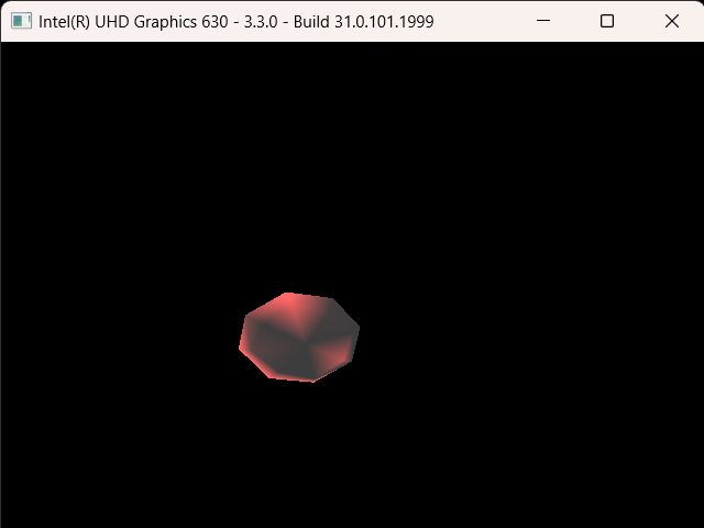
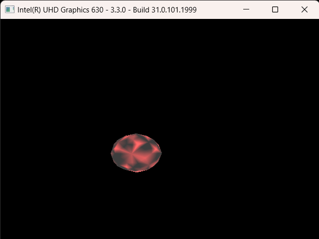
Above are the outputs when the subdivision is applied once and then twice, in order. At first glance, I thought that maybe my algorithm was completely wrong, but I realized that the positions of the vertices seemed to be correct. Moreover, it seemed like for every new face I created half of it would not properly render. Since I had separated each new face into two triangles, I was most likely calculating the normal values incorrectly. Unfortunately, no matter what I did I could not fix this issue.
I was calculating the normals by first calculating the vectors going from the new face point to the edges and the corner. For example, let’s say that the new face I was calculating contained a new face point f, two edge points e1 and e2 that neighbored this face point, and a newly calculated vertex p that was between these two edges. I calculated three vectors: one from point f to point e1 (fe1), another from point f to point p (fp), and a third from point f to point e2 (fe2). Next, I computed the cross-products of the vectors fp and fe1, as well as fe2 and fp. Finally, I took the average of these cross-products and added their values to the normals of these vertices.
As one can tell from the results above, there was something wrong with this process. But as I mentioned before, the positions of the new vertices were, at least seemingly, correct, so there had to be something wrong with my normal calculation, at least that is the only possibility that came to my mind. I tried to switch the ordering when doing the cross-products, and the correctly rendered and incorrectly rendered faces seemed to switch. But for some reason when I kept one of the cross-product operations as it was, the entire object was incorrectly rendered.
I tried various other methods from taking the average of all of the normals of faces that were adjacent to a vertex to rewriting the entire function from scratch, but nothing I tried managed to fix this issue. Unfortunately by this point, I was running out of time, and I still had a lot to do so I decided to move on and maybe take a look again once everything else was done.
For the given assignment, I had to prepare a scene with multiple objects that were doing various movements. I decided to keep it simple and decided that I would add four objects, two of which would move perpendicular to each other and cross paths, and the other two would spin around themselves at opposite corners. It initially looked as it did below, with only an octahedron and a tetrahedron moving perpendicularly to each other:
To render multiple objects with their own vertex and fragment shaders, I used the model class my homework partner and I utilized for our final assignment in the Computer Graphics 1 course. I also had to implement a line mode and a wire mode visualization, which were relatively simple to make. The only issue was that there was some aliasing when the visualization was switched to line mode, and changing the glPolygonOffset did not help. As a small workaround, I instead increased the line width very slightly when drawing in line mode. Below is the visualization of line mode with aliasing:
And below is the version with fixed aliasing:
Once that was done, I implemented the functionality to decrease the subdivision level of the objects. Perhaps this might not be the most optimal solution in terms of memory, but I decided that it would be best to simply store the vertex, face, texture, and normal values of each object at each calculated level and simply reuse them when the subdivision level is decreased or re-increased. I understand that this solution might not translate well to a real-life scenario but since the subdivision operation would only be applied a maximum of four times per object, and my subdivision function was very inefficient, I believed that this would be the best solution.
Now, of course, there was a slight issue initially. When I first implemented this, most of the vertices would disappear when the subdivision level was decreased. By this point, I was a bit sleep-deprived so this situation left me a bit perplexed. The video below shows this error:
When I observed this error with a clearer head, I noticed something important: the remaining vertex count when decreasing the subdivision level is actually the amount it was supposed to be at that level, it was just the information of the vertices, faces, and whatnot that was not being updated. Then it dawned on me.
I had forgotten to re-initialize the models after decreasing the levels.
To say this infuriated me would be an understatement as it took an embarrassingly long time to figure this out, which left me with very little time, and I still had to go over my subdivision implementation again. Luckily I at least managed to finish the rest of the requirements. I think.
Below is how it is actually supposed to look. I also added some shading and a new object to the scene:
As I said before, I had decided that my scene would contain 4 objects, yet I’ve only shown 3 so far. The last one is the cube that I had to include in my scene as an obligation of the assignment. But what I had not known was that this cube consisted of quads instead of triangles. Now, this was actually mentioned to us during the briefing of the assignment, I think, but I had forgotten and had failed to properly read the assignment document, which also mentioned that there would be quad topologies (perhaps I’m legally blind).
Realizing this, I quickly started rewriting my parser function so that it could also parse quad objects. I achieved this by dividing each quad into two triangles and writing them to the buffers. I also kept the information of the quads so that I could use them when calculating the subdivision of the cube.
Below is the scene with the cube added:
Finally, I rewrote the subdivision function so that it could also work on quad topology. Unfortunately, my normal calculations were, again, incorrect so the cube was rendered incorrectly yet again.
Below is a video showcasing the final version of my program:
By this point, I barely had any time so I submitted my homework in this state. There were many things I could have improved, or properly implemented, but I mismanaged my time and underestimated the time needed to complete this homework. But still, I believe it is decent enough for homework that was done in three days, at least considering my own capabilities.