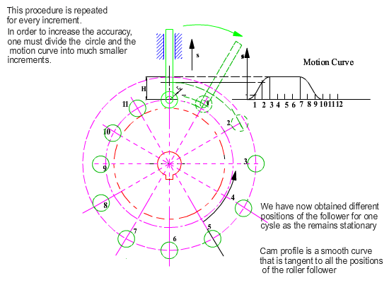
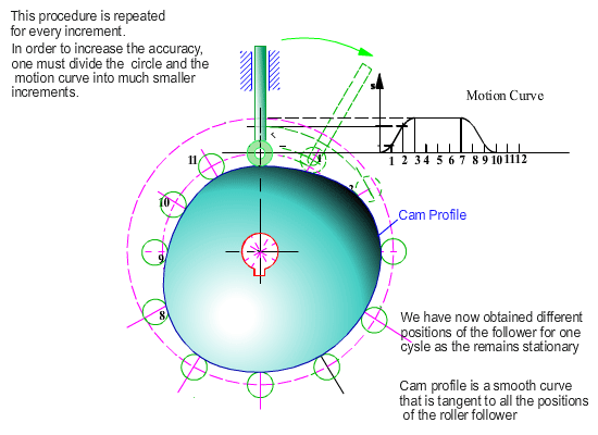
Cam Profile for a Radial Cam With Translating Roller Follower
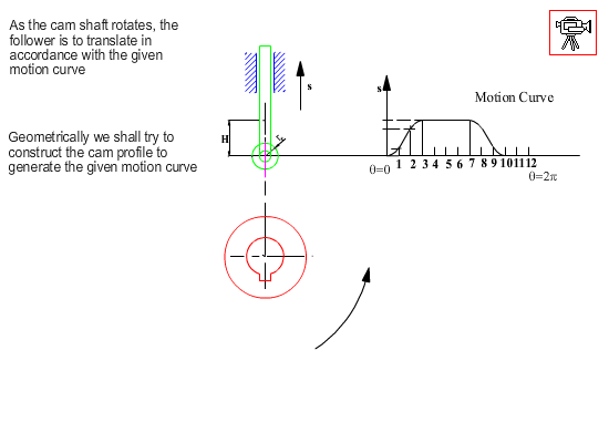
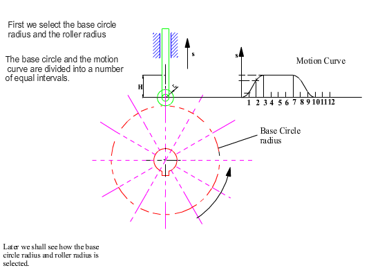
Now let us apply the envelope theory to a basic cam-follower system: a radial cam with a translating roller follower. We shall assume that the follower sliding axis is offset by an amount c from the centre of rotation of the cam (when c = 0, it is an inline follower).
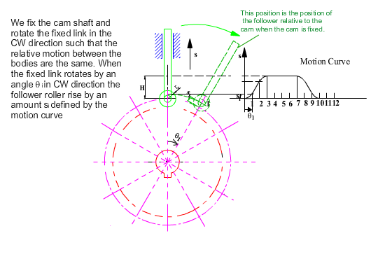
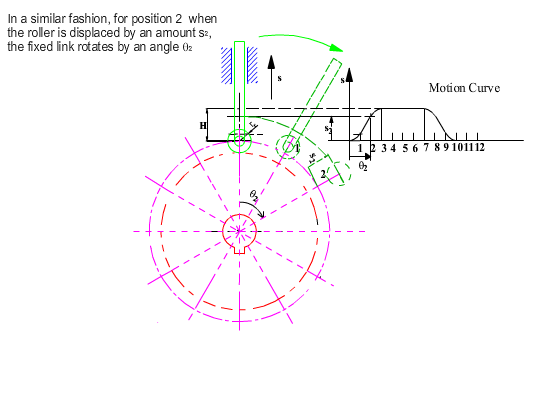
As in the case of geometrical construction, let us use kinematic inversion and fix the cam and release the fixed link. For the same relative motion, if the cam rotates by a counter clockwise angle q, the fixed link will rotate by a clockwise angle q and the follower will be displaced by an amount s(q) with respect to the fixed link as shown. The roller takes different positions for each q angle, hence it is the roller profile that is the generating curve and its equation for any cam angle q is:
| f(x, y, θ) = (x − xp)2 + (y − yp)2 − rr = 0 | (1) |
where rr is the radius of the roller. P(xp, yp) are the coordinates of a point on the pitch curve (the centre of the roller), which is a function of the cam angle q. xp, yp is given by:
|
xp = c cosθ + (k + s) sinθ yp = −c sinθ + (k + s) cosθ |
(2) |
where k = \displaystyle \sqrt{{{{{\left( {{{\text{r}}_{\text{t}}}+{{\text{r}}_{\text{r}}}} \right)}}^{2}}-{{\text{c}}^{2}}}} . (One can also write the coordinates of point P in complex numbers as: z = xp + iyp = ce−iθ + i(k + s)e−iθ. The real and imaginary parts of this complex number will yield xp and yp coordinates as given in equation 2).
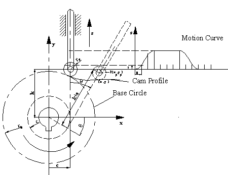
Note that the equation for the roller profile is a generating curve which depends on constant parameters rb, rr, and c and on the follower displacement s and cam rotation angle q. Since s is also a function of q defined by the motion curve, the generating curve (roller profile) is in the form f(x, y, q). Where q is a parameter (for each value of q we obtain a member within the family of curves). Hence the generating curve is:
| f(x, y, θ) = (x − xp)2 + (y − yp)2 − rr = 0 | (3) |
If we take the partial derivative of f(x, y, q) with respect to q :
| fθ(x, y, θ) = −2(x − xp)∂xp/∂θ − 2(y − yp)∂yp/∂θ = 0 | (4) |
In this equation:
|
∂xp/∂θ = (∂s/∂θ − c)sinθ + (k + s)cosθ ∂yp/∂θ = (∂s/∂θ − c)cosθ − (k + s)sinθ |
(5) |
Unlike the previous examples where we were able to eliminate the parameter q from the two equations (Equations 3 and 4), due to the motion curve characteristics, we cannot eliminate the parameter q from the above two equations. Instead, we obtain the envelope equation in parametric form by eliminating y from the two equations (solve for (y − yp) from equation 4 in terms of (x − xp) and substitute into equation 3) we obtain:
| x = xp ± \displaystyle \frac{{{{\text{r}}_{\text{r}}}}}{{\sqrt{{1+{{{\left( {\frac{{\partial {{\text{x}}_{\text{p}}}\text{/}\partial \text{θ}}}{{\partial {{\text{y}}_{\text{p}}}\text{/}\partial \text{θ}}}} \right)}}^{2}}}}}} | (6) |
and solving for y
| y = yp − (x − xp) \displaystyle {\frac{{\partial {{\text{x}}_{\text{p}}}\text{/}\partial \text{q}}}{{\partial {{\text{y}}_{\text{p}}}\text{/}\partial \text{q}}}} | (7) |
The envelope is the cam profile. Note that we have not obtained an explicit expression for the cam profile. Instead we have an algorithm with which we can determine the coordinates on the cam profile in terms of the parameter q, which is the cam rotation angle. Also note that for every cam rotation angle we obtain to points on the profile which means that the envelope is of two parts. One is the inner envelope and the other is the outer envelope (external or internal cam profile).
Example 8.7.
Design a radial cam with an offset roller follower which rises to 50 mm in 120° cam rotation using simple harmonic motion and dwells at 50 mm for 60° cam rotation. For the next 120° cam rotation in simple harmonic motion. Let the roller radius be 20 mm, base circle radius 50 mm and let the eccentricity c = 20 mm.
- Displacement and velocity diagrams:
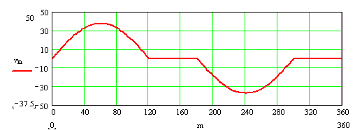
Let us obtain the displacement of the follower and its velocity for every 10° of cam shaft rotation:
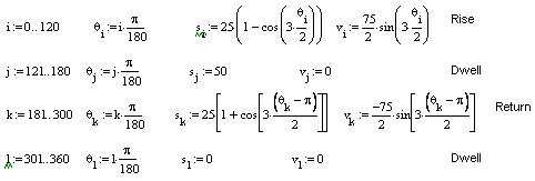
The displacement and velocity diagrams are shown below (we assume w = 1 rad/s, therefore v = ds/dq).
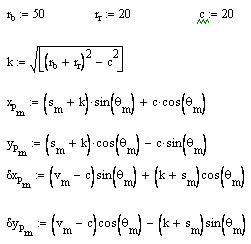
- The coordinates of the centre of the roller and their derivatives with respect to cam angle (use equations 2 and 5) (m is the dummy index: m = 0, 1, …, 360):
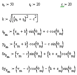
dxp and dyp are the partial derivatives of xp and yp with respect to q.
- Cam profile (use equation 6)

Note that x1, y1 and x2, y2 gives us two pairs of cam profile coordinates depending on the + or − sign in the equation for x. x1, y1 and x2,y2 will be on the inner envelope or on the outer envelope for certain portions of the curve (one cannot state that x1, y1 is on the inner or outer envelope. x1, y1 will lie on the outer envelope for a certain range of q and will lie on the inner envelope for the other range of q). The result is shown below.
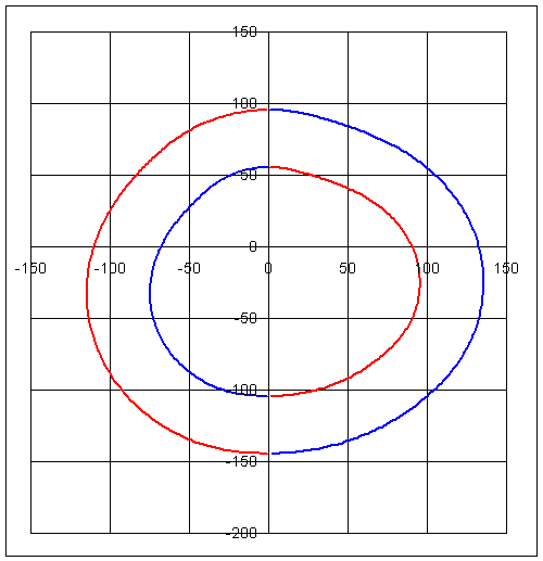
red: x1, y1: blue: x2, y2
If we want to draw the cam profile in external contact with the roller follower, we can convert the cam profile coordinates to polar form and select the coordinate closer to the origin:
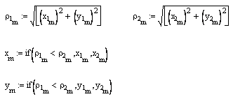

The plot of the cam profile in polar coordinates (r, x) is shown:

One can determine the pressure angle for every position as shown.

Using MathCad:
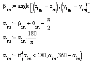
The variation of the pressure angle within one cycle is shown below. Note that with c=20 mm the pressure angle during the rise is within −16° < a < 11° and during the return motion amax = 34°. The pressure angle curve when the eccentricity is zero is also shown. The maximum pressure angle is 22.3° for both rise and return periods. By employing eccentricity, the maximum pressure angle during the rise portion is decreased at the expense of the maximum pressure angle during the return motion (which is less critical).

with eccentricity c = 20 mm

no eccentricity (c = 0)
If you are to cut this cam profile using a cutter of radius of rc (usually rc > rr), then we have to know the centre of the cutter. In such a case the cutter must be tangent to the cam profile. Since the roller has the same tangent at the point of contact due to the envelope theory, the centre of the cutter must be at a distance rc from the point of contact (x, y) and it must be along the line defined by the contact point (x, y) and the centre of the roller (xp, yp)
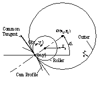
xc = x + rc cosψ
yc = y + rc sinψ
where:
ψ = tan-1[(yp − y)/(xp − x)]
In our example, if we are to cut the cam profile with a cutter diameter of 60 mm, the coordinates of the centre of the cutter will be given by:


The path traced by the center of the cutter (dashed line) and the cam profile is as shown.

