8.4 Cam Size Determination
Cam size determination is related to the determination of the base circle of the cam. In almost all applications we would like to minimize the size of the cam being used. Large cams are not desired due to the following reasons:
1. More space is required.
2. Unbalanced mass increases
3. Follower has a longer path to follow for each cycle. Hence the angular velocity of the follower and the surface velocity increases.
However as we decrease the cam size, the following factors take into effect:
1. The force transmission characteristics deteriorate. The cam profile steepness increases.
2. The curvature of the cam profile decreases (sharp curves)
3. Strength requirements due to the forces and moments acting on the cam.
In practice the cam size is determined by considering two factors: the pressure angle and the minimum radius of curvature..
8.4.1. Pressure Angle
The pressure angle, which is the reciprocal of the transmission angle μ, i.e. α = π/2 – μ, is defined as:
\displaystyle {\tan \text{α}=\frac{\text{Force component tending to apply pressure on the follower bearings}}{\text{Force component tending to move the follower}}}
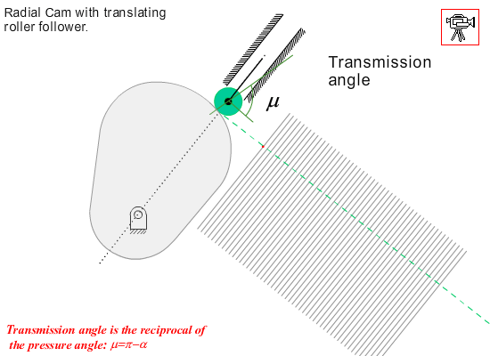
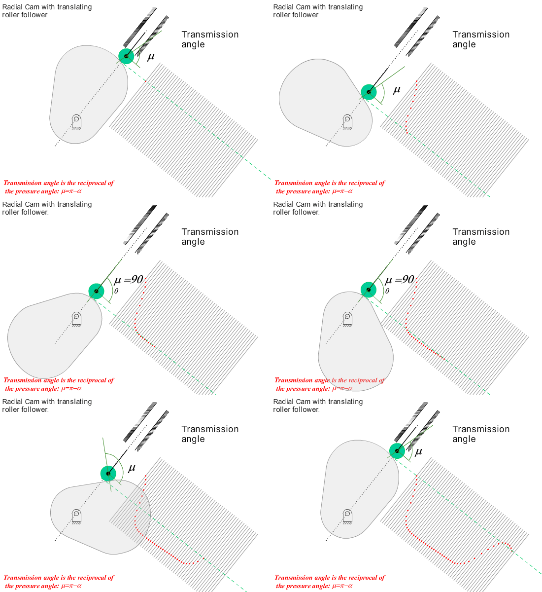
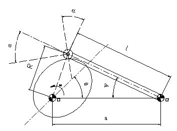
In cams there is point contact between the two profiles. The force is transmitted along the common normal of the two contacting curves. Pressure angle for oscillating and translating roller follower radial cams are shown below. For flat faced followers the pressure is apparently zero at all times (the normal to the profile is normal to the flat face, which is always constant). Curvature characteristics is used for the determination of cam size. In force closed cams, the pressure angle is important during the rise portion where cam is driving the follower, in return motion it is the spring force (or any other force used for forced closure) that lowers the follower.
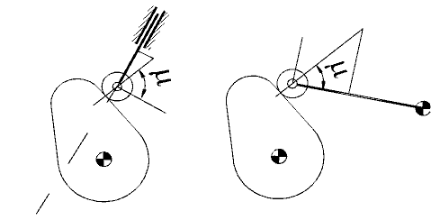
The pressure angle is a function of cam rotation angle. We can express the force ratio expression for the pressure angle using the kinematics of the mechanism.
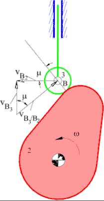 Consider an inline translating roller follower radial cam . The pressure angle is a function of cam rotation and the amount of rise, s (which is also a function of the cam rotation angle). At the instant considered, velocity of point B on link 3 (follower) will be vB3 along the slider axis (vertical). The velocity of a point B on link 2 (cam) at this instant is vB2 perpendicular to the line OB. These two velocities are related by the equation (see Chapter 4):
VB3 = VB2 + VB3/B2
In this equation:
VB3: Follower speed with magnitude = ds/dt
VB2: Velocity of point B on the cam with magnitude = rω (r = |OB| = s + rb + rr, rb is the base circle radius, rr is the roller radius).
The relative velocity direction is along the path tangent. Hence we have:
\displaystyle \tan {\text{α}}=\frac{{{{\text{V}}_{{\text{B}3}}}}}{{{{\text{V}}_{{\text{B}2}}}}}=\frac{{\text{ds/dt}}}{{\text{rω}}}=\frac{\text{ds/dθ}}{{\text{r}}}
Here s′ is the derivative of s with respect to θ. If the motion curve is known, the pressure angle variation can be determined (at the dwell periods note that tanα = 0 or α = 0, no motion is transmitted). During the rise or return portion s(θ) is monotonically increasing or decreasing. Except the double harmonic, for symmetric curves, s′(θ) is maximum at the midpoint (s = H/2, θ = β/2). Hence the pressure angle is maximum or minimum at half the rise or return motion for inline roller followers. It will be given by the equation:
\displaystyle \tan {{\text{α}}_{\max}}=\frac{{\left( {\text{ds/dθ}} \right)}_{\max}}{\text{H/2}+{\text{r}}_{\text{r}}+{\text{r}}_{\text{b}}}
Since (ds/dθ)max = CvH/β, this value can easily be determined for a given motion curve. Usually rr is determined from strength considerations. The designer selects an acceptable maximum pressure angle and solves the above expression for the base circle radius.
Maximum pressure angle usually depends on the speed, load and place of application of the cam mechanism. In the literature as a rule of thumb:
If the cam speed is less then 30 rpm: αmax ≤ 45°
If the cam speed is greater then 30 rpm: αmax ≤ 30°
If the follower is eccentric as shown in the figure, then the pressure angle is given by the equation:
\displaystyle \tan {\text{α}}=\frac{{\text{ds/dθ}}-{\text{e}}}{{\text{s(θ)}}+{\text{c}}}
where e is the eccentricity and \displaystyle \text{c}=\sqrt{{{\text{r}}_{\text{b}}}^{2}-{\text{e}}^{2}} or \displaystyle {\text{r}}_{\text{b}}=\sqrt{{\text{c}}^{2}+{\text{e}}^{2}}
In force closed cams the follower is driven by the cam during the rise portion. In the return motion it is the spring force (or weight) that drives the follower towards the cam surface, hence the pressure angle is not that critical. Using eccentricity, for the same can size one can reduce the pressure angle during the rise while there is some increase of pressure angle during the return, or for the same pressure angle a smaller cam size can be used.
Example 8.3.
Determine the minimum radius of the base circle for the cam motion given in Example 8.2, assuming an inline roller follower radial cam, with maximum permissible pressure angle 26°.
Since the rise is in cycloidal motion, Cv = 2. Hence:
(ds/dθ)max = CvH/β = 2(40)/(2π/3) = 120/π = 38.20 mm
Hence:
(rb + H/2 + rr) tanamax = 38.20 or rb + 20 + rr = 38.20/tan(26°) = 78.32 mm ⇒ rb + rr = 58.32 mm
If the roller radius is 10 mm (rr = 10 mm) then a base circle radius of 50 mm (rb = 50 mm) will be an acceptable choice for the cam.
In case of oscillating roller followers, the pressure angle is given by:
\displaystyle {\text{α}}={\text{σ}}\left[{\frac{\text{π}}{2}}-{\text{sin}}^{-1}\left( {\frac{\text{a}}{\text{R}}} \right)\right]+{\text{tan}}^{-1}\left[{\frac{1}{\frac{\text{R}^2}{\text{laϕ}^\prime\sin\text{ψ}}-\frac{\text{a}^2-\text{R}^2-\text{l}^2}{2\text{Ra}\sin\text{η}}}}\right]
where σ = +1 or −1 if the cam is rotating away or towards the follower arm pivot. For example, for a counter clockwise rotating cam σ = 1. If the cam is rotated clockwise then s = −1.
\displaystyle {\text{R}}=\sqrt{\text{l}^2+\text{a}^2-\text{2la}\cos\text{ψ}}
\displaystyle {\text{η}}={\text{cos}}^{-1}\left[\frac{\text{a}^2+\text{R}^2-\text{l}^2}{\text{2aR}}\right]
ψ(θ) = ϕ0 + ϕ(θ), where ϕ(θ) is the motion curve, ϕ′ = dϕ/dθ and ϕ0 is the value of the angle ψ when the roller is on the base circle:
\displaystyle {\text{ϕ}}_{\text{0}}={\text{cos}}^{-1}\left[\frac{{{\text{r}}_{\text{b}}}^2+\text{l}^2-\text{a}^2}{\text{2al}}\right]
8.4.2. Cam Curvature
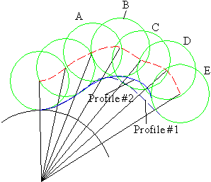
In practice for roller followers it is common to determine the cam size using the maximum pressure angle criteria and then check that the cam curvature is satisfactory. In case of flat faced followers, the cam curvature is the determining criteria for the cam size. Graphically when laying out the cam profile, first the successive positions of the follower according to the cam motion curve is drawn while keeping the cam fixed. Consider the case shown below. According to the cam motion requirements, with the selected roller radius and base circle radius the positions of the roller are A, B, C, D and E. It is not possible to draw a smooth curve that is tangent to all the roller circles. With Profile#1, the cam profile is tangent to the circles at positions A, C and E, and in Profile#2 the cam profile is tangent to positions A, B and E of the roller. There is no cam profile that will be tangent to all the positions of the roller. This is known as “undercutting” and occurs whenever the radius of curvature of the cam profile is less than the radius of the roller (ρp < rr). The only way to eliminate this condition is that one must select a larger base circle radius or (if strength conditions permit) reduce the radius of the roller.
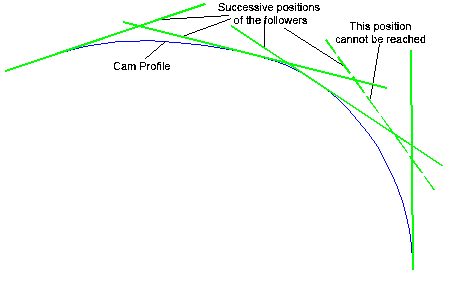
A similar case is shown in case of flat faced followers. The cam profile is not tangent to all the successive positions of the follower.
The radius of curvature of a curve in plane is given in polar coordinates as:
\displaystyle {\text{ρ}}=\frac{{\left[{\text{r}}^2+{\left({\text{dr/dθ}}\right)}^2\right]}^{\text{3/2}}}{{\text{r}}^2+2{\left({\text{dr/dθ}}\right)}^2-{\text{r}}\left({\text{d}}^2{\text{r}}/{\text{d}}{\text{θ}}^2\right)}
For a radial cam with roller follower the radius of curvature of the pitch curve (the curve described by the centre of the roller follower, when the cam is fixed) will be given by:
\displaystyle {\text{ρ}}_{\text{p}}=\frac{{\left[{\left({\text{r}}_{\text{b}}+{\text{r}}_{\text{r}}+{\text{s}}\right)}^2+{\left({\text{ds/dθ}}\right)}^2\right]}^{\text{3/2}}}{{\left({\text{r}}_{\text{b}}+{\text{r}}_{\text{r}}+{\text{s}}\right)}^2+2{\left({\text{ds/dθ}}\right)}^2-\left({\text{r}}_{\text{b}}+{\text{r}}_{\text{r}}+{\text{s}}\right)\left({\text{d}}^2{\text{s}}/{\text{d}}{\text{θ}}^2\right)}
As a rule of thumb for roller followers the following recommendations are made to avoid undercutting:
- Use smaller roller diameter (this is limited by the contact stress at the surface)
- Utilize a larger cam size (this is usually not desired. It must be applied if necessary)
- Employ an internal cam (the curvature is less critical but they are more expensive to manufacture)
For flat faced follower, the radius of curvature will be given by:
\displaystyle {\text{ρ}}=\frac{{\left[{\left({\text{r}}_{\text{b}}+{\text{s}}\right)}^2+{\left({\text{ds/dθ}}\right)}^2\right]}^{\text{3/2}}}{{\left({\text{r}}_{\text{b}}+{\text{s}}\right)}^2+2{\left({\text{ds/dθ}}\right)}^2-\left({\text{r}}_{\text{b}}+{\text{s}}\right)\left({\text{d}}^2{\text{s}}/{\text{d}}{\text{θ}}^2\right)}
The location of the contact point P on the follower can be written in complex numbers as:
\displaystyle \overrightarrow{{\text{OP}}}={\text{X}}+\left( {{{\text{r}}_{\text{b}}}+{\text{s}}} \right){\text{i}}
or
\displaystyle \overrightarrow{{\text{OP}}}=\overrightarrow{{\text{OC}}}+{\text{ρi}}={{\text{r}}_{\text{C}}}{{\text{e}}^{{{\text{i}}\left({\text{α}}+{\text{θ}}\right)}}}+{\text{ρi}}={{\text{r}}_{\text{C}}}\cos \left({\text{α}}+{\text{θ}}\right)+\left[ {{{\text{r}}_{\text{C}}}\sin \left({\text{α}}+{\text{θ}}\right)+{\text{ρ}}} \right]{\text{i}}
Equating the real and imaginary parts:
\displaystyle {\text{X}}={{\text{r}}_{\text{C}}}\cos \left({\text{α}}+{\text{θ}}\right) ; \displaystyle {\text{r}}_{\text{b}}+{\text{s}}={\text{r}}_{\text{C}}\sin \left({\text{α}}+{\text{θ}}\right)+{\text{ρ}}
Noting that the centre of curvature does not change for an infinitesimal motion, the first rates of change of rC and a with respect to θ is zero. Taking the derivative of \displaystyle \overrightarrow{{\text{OP}}} with respect to θ yields:
\displaystyle \frac{{\text{dX}}}{{\text{dθ}}}+\frac{{\text{ds}}}{{\text{i}}}=-{{\text{r}}_{\text{C}}}\sin \left({\text{α}}+{\text{θ}}\right)+{\text{r}}_{\text{C}}\cos \left({\text{α}}+{\text{θ}}\right){\text{i}}
or dX/dθ = −rCsin(α + θ) ds/dθ = rCcos(α + θ)
Also X = ds/dθ. Differentiating: dX/dθ = d2s/dθ2. Now, rb + s = −d2s/dθ2 + ρ or
ρ = rb + s + d2s/dθ2
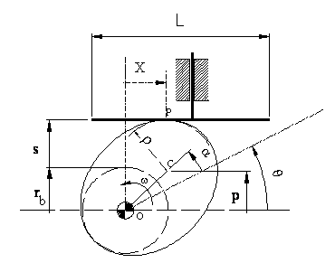
From the above equations we can conclude:
- Xmax = (ds/dθ)max and Xmin = (ds/dθ)min (maximum velocity during the return motion), hence the length of the follower L = Xmax − Xmin.
- The minimum radius of curvature is when d2s/dθ2 is at its minimum (largest negative value). The radius of curvature must always be greater than zero (when ρ = 0, the curve has a cusp).
