The Classical Transmission Angle Problem:
The classical transmission angle problem can be stated as follows:
“Determine the crank-rocker proportions of a four-bar mechanism with a given swing angle (ψ) and corresponding crank rotation (ϕ), or time ratio, such that the maximum deviation of the transmission angle from 90° is minimum.”
The problem can be considered in two parts. The first part is the synthesis problem in which one must determine four-bar mechanisms with crank-rocker proportions that must have a given swing angle and a corresponding crank rotation. There is an infinite set of solutions for this part of the problem. The second part of the problem is concerned with the optimisation. Out of the infinite possible solutions obtained in the first part, one must determine a particular four-bar mechanism whose maximum transmission angle deviation from 90° is a minimum.

For the first part of the problem consider the two dead center positions of the crank-rocker mechanism (see figure above). We can write the loop closure equations for these two particular positions (note that the coupler and the crank are collinear at the dead-centers).
| a2eiβ + a3eiβ = a1 + a4eiψ1 | (7) |
| a2ei(β + ϕ) + a3ei(β + ϕ − π) = a1 + a4ei(ψ1 + ψ) | (8) |
Rearranging:
| (a2 + a3)eiβ − a4eiψ1 = a1 | (9) |
| (a2 − a3)eiβeiϕ − a4eiψ1eiψ = a1 | (10) |
Let us define Z1, Z2 and λ as:
Z1 = a2eiβ
Z2 = a4eiψ1
λ = a3/a2
Z1 and Z2 are complex numbers which represent the vectors A0Ae and B0Be and λ is the ratio of the coupler link to the crank length. Without loss of generality we can let a1 = 1 unit (this correspond to the scaling of the mechanism). Now the loop closure equations (9) and (10) for the dead-center positions can be written in “normalised form” as:
| (1 + λ)Z1 − Z2 = 1 | (11) |
| eiϕ(1 − λ)Z1 − Z2eiψ = 1 | (12) |
Unlike the use of the loop equations for kinematic analysis, now ϕ and ψ are the given swing angle and corresponding crank rotation for which we have to determine the mechanism proportions. The two complex equations are linear in terms of the unknowns Z1 and Z2 the solution of which is:
| \displaystyle {{\text{Z}}_{1}}=\frac{{1-{\text{e}^{{\text{iψ}}}}}}{{{\text{e}^{{\text{iϕ}}}}-{\text{e}^{{\text{iψ}}}}-\text{λ}\left( {{\text{e}^{{\text{iϕ}}}}+{\text{e}^{{\text{iψ}}}}} \right)}}={{\text{a}}_{2}}{\text{e}^{{\text{iβ}}}} | (13) |
| \displaystyle {{\text{Z}}_{2}}=\frac{{1-{\text{e}^{{\text{iψ}}}}+\text{λ}\left( {1+{\text{e}^{{\text{iψ}}}}} \right)}}{{{\text{e}^{{\text{iϕ}}}}-{\text{e}^{{\text{iψ}}}}-\text{λ}\left( {{\text{e}^{{\text{iϕ}}}}+{\text{e}^{{\text{iψ}}}}} \right)}}={{\text{a}}_{4}}{\text{e}^{{{{\text{iψ}}_{1}}}}} | (14) |
As λ changes from minus infinity to plus infinity, Z1 and Z2 describe a curve which is the loci of the tip of the vectors A0Ae and B0Be. According to equations (13) and (14), these loci are two circles for any given value of ϕ and ψ. For ϕ = 160° and ψ = 80° these two circles are as shown below (in order to draw the two circles with the same reference frame, A0 as the origin and the real axis is along A0B0; instead of Z2, the vector 1 + Z2 is drawn). There is an infinite set of solutions and these can be obtained by drawing a line from A0 making any angle β with respect to A0B0. The intersection of this line and the circles are Ae and Be respectively. Geometrically, the link lengths can be found from the figure as |A0Ae| = a2, |AeBe| = a3, |B0Be| = a4, |A0B0| = a1 = 1.
Analytically, we can determine a2, a4, and a3 (= λa2) for any value of λ, ψ and ϕ using equations (13) and (14) as:
\displaystyle {{\text{a}}_{2}}^{2}={{\text{Z}}_{1}}\overline{{{{\text{Z}}_{1}}}}
\displaystyle {{\text{a}}_{4}}^{2}={{\text{Z}}_{2}}\overline{{{{\text{Z}}_{2}}}}
a3 = λa2
a1 = 1


The link lengths are functions of the variable parameter λ, the given swing angle and the corresponding crank rotation (ϕ and ψ). For crank rocker proportions a necessary (but not sufficient) condition is λ > 1 (why??). One can use the initial crank angle b as the free parameter rather than λ. In such a case the link lengths are given by the following equations:
| \displaystyle {{\text{a}}_{2}=-\sin\left( \frac{\text{ψ}}{2}\right)\frac{{\cos\left( {\frac{\text{ϕ}}{2}+\text{β}} \right)}}{{\sin\left( {\frac{{\text{ϕ}-\text{ψ}}}{2}} \right)}}} | (15) |
| \displaystyle {{\text{a}}_{3}}=+\sin\left( \frac{\text{ψ}}{2}\right)\frac{{\sin\left( {\frac{\text{ϕ}}{2}+\text{β}} \right)}}{{\cos\left( {\frac{{\text{ϕ}-\text{ψ}}}{2}} \right)}} | (16) |
| a42 = (a2 + a3)2 + 1 − 2(a2 + a3)cosβ | (17) |
| a1 = 1 |
One can either use λ or β as a free parameter and obtain different four-bar mechanism proportions. The mechanism proportions that are of crank rocker type will all have the given swing angle and corresponding crank rotation. In order to obtain crank rocker proportions we have limits on swing angle and corresponding crank rotation as:
0° < ψ < 180°
90° + ψ/2 < ϕ < 270° + ψ/2
If we let:
t = tan(ϕ/2) , u = tan[(ϕ − ψ)/2] , v = tan(ψ/2)
The link lengths can be expressed as:
| \displaystyle {{\text{a}}_{1}}^{2}=\frac{{{{\text{u}}^{2}}+{{\text{λ}}^{2}}}}{{1+{{\text{u}}^{2}}}} | (18) |
| \displaystyle {{\text{a}}_{2}}^{2}=\frac{{{{\text{v}}^{2}}}}{{1+{{\text{v}}^{2}}}} | (19) |
| \displaystyle {{\text{a}}_{3}}^{2}={\text{λ}}^{2}{{\text{a}}_{2}}^{2}=\frac{{\text{λ}}^{2}{\text{v}}^{2}}{{1+{{\text{v}}^{2}}}} | (20) |
| \displaystyle {{\text{a}}_{4}}^{2}=\frac{{{{\text{t}}^{2}}+{{\text{λ}}^{2}}}}{{1+{{\text{t}}^{2}}}} | (21) |
Example:
Determine the proportions of a four-bar mechanism of 120 mm fixed link length and with ψ = 40° and ϕ = 160°.
- Let us select the initial crank angle β = 60°. Using equations (15)-(17):
\displaystyle {{\text{a}}_{2}}=-\sin \left( {20{}^\circ } \right)\frac{{\cos \left( {80{}^\circ +60{}^\circ } \right)}}{{\sin \left( {80{}^\circ -20{}^\circ } \right)}}=0.30254
\displaystyle {{\text{a}}_{3}}=\sin \left( {20{}^\circ } \right)\frac{{\sin \left( {80{}^\circ +60{}^\circ } \right)}}{{\cos \left( {80{}^\circ -20{}^\circ } \right)}}=0.43969
and
a42 = (0.30254 + 0.43969)2 + 1 − 2(0.30254 + 0.43969)cos60° = 0.80867 ⇒ a4 = 0.89926
For a1 = 120 mm, the link lengths are a2 = 36.3 mm, a3 = 52.76 and a4 = 107.91 mm.
The maximum deviation of the transmission angle from 90° will be (Eq. (4)):
\displaystyle {\cos \text{μ}_{\begin{smallmatrix} \text{min} \\ \text{max} \end{smallmatrix}}=\frac{{107.91}^{2}+{52.76}^{2}-{120}^{2}-{36.30}^{2}}{2 \cdot 107.91 \cdot 52.76} \pm \frac{120 \cdot 36.30}{107.91 \cdot 52.76}=-0.113247 \pm 0.765106}
from which we obtain μmax = 151.44° (D1 = 61.44°) and μmin = 49.32° (D2 = 40.68°). Since μmax deviates by 61.44° from right angle, μmax is the critical transmission angle.
b) If we select λ = 1.4, using equations (18)-(21):
t = tan(80°) = 5.671282 , u = tan(60°) = 1.732051 , v = tan(20°) = 0.36397
\displaystyle {{\text{a}}_{1}}^{2}=\frac{{{{{1.732051}}^{2}}+{{{1.4}}^{2}}}}{{1+{{{1.732051}}^{2}}}}=1.24\text{ }\Rightarrow \text{ }{{\text{a}}_{1}}=1.113553
\displaystyle {{\text{a}}_{2}}^{2}=\frac{{{{{0.363970}}^{2}}}}{{1+{{{0.363970}}^{2}}}}=0.116978\text{ }\Rightarrow \text{ }{{\text{a}}_{2}}=0.342020
\displaystyle {{\text{a}}_{3}}=1.4\cdot 0.342020=0.478828
\displaystyle {{\text{a}}_{4}}^{2}=\frac{{{{{5.671282}}^{2}}+{{{1.4}}^{2}}}}{{1+{{{5.671282}}^{2}}}}=1.028948\text{ }\Rightarrow \text{ }{{\text{a}}_{4}}=1.0114371
For a1 = 120 mm; a2 = (0.342020/1.113553)×120 = 36.86 mm, a3 = 51.60 mm, a4 = 109.31 mm. The critical transmission angles will be:
\displaystyle {\cos \text{μ}_{\begin{smallmatrix} \text{min} \\ \text{max} \end{smallmatrix}}=\frac{{{{{109.31}}^{2}}+{{{51.60}}^{2}}-{{{120}}^{2}}-{{{36.86}}^{2}}}}{{2\cdot 109.31\cdot 51.60}}\pm \frac{{120\cdot 36.86}}{{109.31\cdot 51.60}}=-0.101715 \pm 0.784200}
from which we obtain μmax = 152.36° (D1 = 62.36°) and μmin = 49.96° (D2 = 43.04°). Since μmax deviates by 62.36° from right angle, μmax is the critical transmission angle.
In the second part of the problem, amongst the infinite set of solutions for a given swing angle and crank rotation, one must select the one for which the maximum deviation of the transmission angle from 90° is a minimum. Substituting the link lengths expressed in terms of a single parameter (λ), into the equation for minimum (or maximum) transmission angle (equation (4)):
| \displaystyle {\cos \text{μ}_{\begin{smallmatrix} \text{min} \\ \text{max} \end{smallmatrix}}=\frac{{{{\text{a}}_{3}}^{2}+{{\text{a}}_{4}}^{2}-{{\text{a}}_{1}}^{2}-{{\text{a}}_{2}}^{2}}}{{2{{\text{a}}_{3}}{{\text{a}}_{4}}}} \pm \frac{{{{\text{a}}_{1}}{{\text{a}}_{2}}}}{{{{\text{a}}_{3}}{{\text{a}}_{4}}}}} | (5) |
which will be a function of λ only. One can determine the value of λ (λopt) which minimises the maximum deviation of the transmission angle by setting the derivative of the transmission angle μ with respect to λ in equation (4) to zero. The value of λopt is then obtained from the solution of the cubic equation:
| Q3 + 2Q2 − t2Q − t2(1 + t2)/u2 = 0 | (22) |
where Q = t2/λopt2. The positive real root between 1/u2 < Q < t2 yields the four-bar mechanism with crank rocker proportions for which the maximum deviation of the transmission angle is a minimum and which satisfies the given swing angle and corresponding crank rotation.
Analytical solution of cubic equations is possible. Alternatively, one can use the root finding routines available in MathCAD or MATLAB or use Goal Seek and Solver tools in Excel to determine the correct root of this cubic. A simple numerical solution for the root of the cubic equation can be obtained by applying Newton-Raphson method. Making an initial guess for the root at the mid point of the interval 1/u2 < Q < t2 (i.e. Q0 = (1/u2 + t2)/2) and refining the estimate on the root Q by the recursion formula:
| \displaystyle {{Q}_{{i+1}}}=\frac{{2{{Q}_{i}}\left( {{{Q}_{i}}+1} \right)+{{\text{t}}^{2}}\left( {1+{{\text{t}}^{2}}} \right)/{{\text{u}}^{2}}}}{{{{Q}_{i}}\left( {3{{Q}_{i}}+4} \right)-{{\text{t}}^{2}}}} | (23) |
The iteration can be stopped when (Qi+1 – Qi)/Qi is a sufficiently small number (say 10-6).
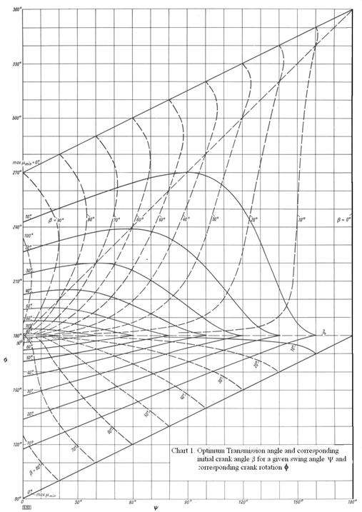
The solution for optimum transmission angle for given swing angle corresponding crank rotation is shown in a chart form in Chart 1 (this chart is known as Alt chart and is given in VDI 2130 standard). From these charts the value of β and max(μmin) can be obtained and the link lengths can also be found using the equations which express the link lengths in terms of β.
Example:
Determine the proportions of a four-bar mechanism of 120 mm fixed link length and with ψ = 40° and ϕ = 160° and for which the maximum deviation of the transmission angle from 90° is a minimum.
Noting that t = 5.671282 and u = 1.732051, 0.333333 < Q < 32.163437. Let us assume Q0 = 16.248. The values for seven iterations are:
| i | 0 | 1 | 2 | 3 | 4 | 5 | 6 | 7 |
| Q | 16.248 | 11.47207 | 8.095663 | 7.982059 | 7.857866 | 7.855707 | 7.855706 | 7.855706 |
Therefore Q = 7.855706 is correct to at least six significant digits. Using λopt = 2.023432, the link lengths are:
\displaystyle {{\text{a}}_{1}}^{2}=\frac{{{{{1.732051}}^{2}}+{{{2.023432}}^{2}}}}{{1+{{{1.732051}}^{2}}}}=1.773569\text{ }\Rightarrow \text{ }{{\text{a}}_{1}}=1.331754
\displaystyle {{\text{a}}_{2}}^{2}=\frac{{{{{0.363970}}^{2}}}}{{1+{{{0.363970}}^{2}}}}=0.116978\text{ }\Rightarrow \text{ }{{\text{a}}_{2}}=0.342020
\displaystyle {{\text{a}}_{3}}=2.023432\cdot 0.342020=0.692054
\displaystyle {{\text{a}}_{4}}^{2}=\frac{{{{{5.671282}}^{2}}+{{{2.023432}}^{2}}}}{{1+{{{5.671282}}^{2}}}}=1.093304\text{ }\Rightarrow \text{ }{{\text{a}}_{4}}=1.045612
For a1 = 120 mm: a2 = (0.342020/1.331754)×120 = 30.82 mm a3 = 62.36 mm, a4 = 94.22 mm. The maximum deviation of the transmission angle from 90° will be:
\displaystyle {\cos \text{μ}_{\begin{smallmatrix} \text{min} \\ \text{max} \end{smallmatrix}}=\frac{{{{{94.22}}^{2}}+{{{62.36}}^{2}}-{{{120}}^{2}}-{{{30.82}}^{2}}}}{{2\cdot 94.22\cdot 62.36}}\pm \frac{{120\cdot 30.82}}{{94.22\cdot 62.36}}=0.219938\pm 0.629455}
from which we obtain μmax = 114.17° (D1 = 24.17°) and μmin = 31.85° (D2 = 58.15°). Since μmin deviates most, μmin is the critical transmission angle. If we refer to Chart 1, we see that for ψ = 40° and ϕ = 160°, max(μmin) = 32° and β = 50.5°. Using the formula for the link lengths: a1 = 1, a2 = 0.2565, a3 = 0.5201 and a4 = 0.784. For a1 = 120 mm; a2 = 30.78 mm, a3 = 62.41 mm and a4 = 94.08 mm. The final mechanism is shown below.

In the solution of the transmission angle problem, there are two special cases. One special case occurs when ϕ = 180° (centric four-bar), for which the maximum and minimum values of the transmission angle is:
\displaystyle {\cos \text{μ}_{\begin{smallmatrix} \text{min} \\ \text{max} \end{smallmatrix}}= \pm \frac{{{{\text{a}}_{1}}{{\text{a}}_{2}}}}{{{{\text{a}}_{3}}{{\text{a}}_{4}}}}}
If the maximum deviation of the transmission angle is to be minimised, then a2 = 0 (since a1 = 1), a4 = 0 and a3 = 1, which is physically impossible four-bar mechanism proportion. In this case, we search for a crank-rocker mechanism for which the transmission angle deviation is of reasonable magnitude while the ratio of the link lengths are of acceptable proportions (the transmission angle will improve as λ or β increases). Using equations (15)-(17) we obtain the link lengths in terms of initial crank angle and the swing angle (ϕ = 180°) as:
\displaystyle \frac{\text{a}_2}{\text{a}_1}=\text{tan}(\text{ψ}/2)\text{sinβ}
\displaystyle \frac{\text{a}_3}{\text{a}_1}=\text{cosβ}
\displaystyle \frac{\text{a}_4}{\text{a}_1}=\frac{\text{sinβ}}{\text{cos}(\text{ψ}/2)}
Substituting the link ratios into into the expression for cosμmin:
\displaystyle \cos \text{μ}_\text{min}=\frac{\text{tan}(\text{ψ}/2)\text{sinβ}}{\text{cosβ}\frac{\text{sinβ}}{\text{cos}(\text{ψ}/2)}}=\frac{\text{sin}(\text{ψ}/2)}{\text{cosβ}}
Now the link lengths ratios can be expressed in terms of minimum transmission angle μmin as:
\displaystyle \text{cosβ}=\frac{\text{sin}(\text{ψ}/2)}{\cos \text{μ}_\text{min}}
In the chart below, the change of the link length ratios a4/a1 and a2/a1 as a function of the swing angle is shown for different minimum transmission angle values. For example, for ψ = 90° the best minimum transmission angle (with a4/a1 = 0 and a2/a1 = 0) is 45°. By reducing the transmission angle to 40° from the chart a4/a1 ≈ 0.54 and a2/a4 ≈ 0.38. Using the equations for μmin = 40°, ψ = 90° yield (to five digit accuracy): a4/a1 = 0.54398, a3/a1 = 0.92306 and a2/a1 = 0.38463. If the transmission angle is 43° then a4/a1 = 0.25970, a3/a1 = 0.98299 and a2/a1 = 0.18363. A higher transmission angle will result with a smaller crank and rocker and the coupler and the fixed link ratio close to unity. Note that for any crank-rocker mechanism μmin < π/2 – ψ/2 i.e. for 90° swing angle the transmission angle cannot be greater than 45° (this statement is true for any corresponding crank angle rotation, ϕ. For a given swing angle centric four-bar will have a better force transmission characteristics).
Another special case is when ϕ – ψ = 180°. The transmission angle deviation is optimum when \displaystyle {{\text{λ}}_{{\text{opt}}}}=\sqrt {1+\frac{1}{{\sin \left( {\text{ψ}/2} \right)}}} . The link lengths are:
a1 = 1
\displaystyle {\text{a}_{2}}=\sin \left( {\text{ψ}/2} \right)
\displaystyle {\text{a}_{3}}=\sqrt{{{\text{a}_{2}}\left( {1+{\text{a}_{2}}} \right)}}
\displaystyle {\text{a}_{4}}=\sqrt{{1+{\text{a}_{2}}}}
![]()
![]()
![]()
![]()