Example 1

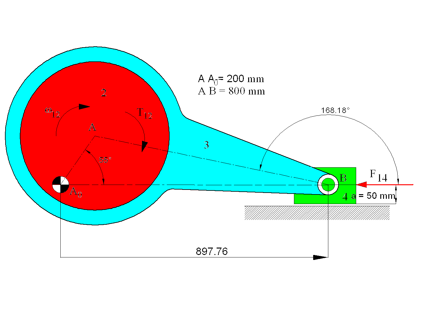
Figure shows a centric slider-crank mechanism. Assume μ = 0.1 for all joints. Determine the joint forces and the input torque T12 required for static equilibrium when θ12 = 55° and the eccentric is rotating CW. The radius of the eccentric is 250 mm and the radius of the other two revolute joint (between links 1-2 and 3-4) are 50 mm. This problem will be solved both graphically and analytically.
From kinematic analysis when θ12 = 55°, θ13 = 168.183° and |A0B| = 897.76 mm (this analysis was performed geometrically using AutoCAD). The free-body diagrams of the links are drawn.

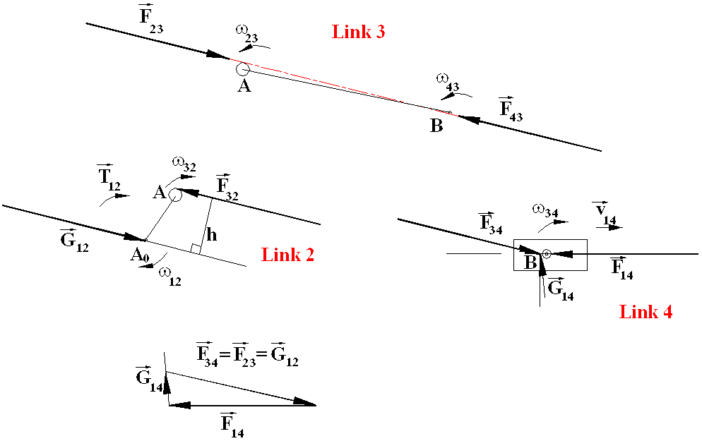
The resisting forces or moments are also shown on the free-body diagrams. Note that the magnitudes of the forces are considered to be positive in the directions shown on the free-body diagrams. In the graphical solution, the first step is to determine the friction circles for the revolute joints. Friction circles of radius μr is drawn at the joints (μr = 25 mm at A and μr = 5 mm at A0 and B). The friction angle for the sliding joint between 1 and 4 is determined. Note that except the eccentric, for a joint with 50 mm radius, the friction circle of 5 mm radius can usually be neglected when the dimensions of the links are considered. For the eccentric, the friction circle is of a considerable size.
The next step is to determine the relative angular and linear displacements between the links connected by the joints. Since link 2 is rotating CW with respect to the fixed link, the relative motions between the links must be found and indicated on the free-body diagrams since this will effect the lines of action of the joint forces.
Consider link 3, it is a two-force member. Furthermore, it is in compression (if you are in doubt, you must perform a force analysis without friction). The forces will be tangent to the friction circles so as to oppose the motion. Therefore F23 will be tangent to the friction circle from the bottom and F43 will be tangent from above. Hence the line of action of F43 = −F43 = −F23 = F32 will be determined, which can be shown on the free-body diagrams of links 2 and 4. Considering link 4, since it is a three-force member, the point of concurrency will be determined as the intersection of the lines of action of the forces F14 and F34. G14 has to pass through this point and must be inclined to the normal of the slider axis by an angle ϕ (where tanϕ = μ = 0.1, or ϕ = 5.71°) such as to oppose the motion. Hence one can draw the force polygon for the force equilibrium equation of link four:
F14 + F34 + G14 = 0
From the force polygon for F14 = 100 N ∠180°, F34 = 105.7 N ∠−14.01° and G14 = 25.7 N ∠5.71°. Considering the free body diagram of link 2, it is a two force and a moment member. The forces are equal and opposite and the moment of the couple is equal to the torque applied. Therefore:
G12 = −F32 = −F23
and
T12 = h F23
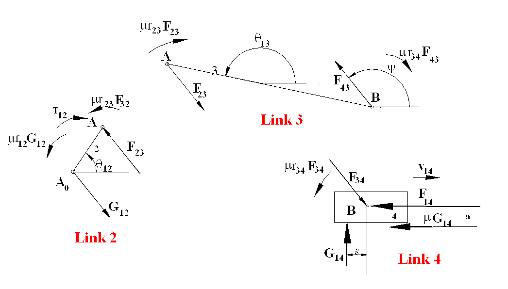
From the figure h = 216 mm. Hence T12 = 22.9 N·m (CW). If the same procedure is to be carried out analytically, rather than the friction circles at the revolute joints, one must place the friction moments on the free body diagrams. These friction moments must always oppose the relative motion. The free body diagrams will be as shown.

For link 4:
SFx = −F34cosϕ − μG14 − F14 = 0
SFy = −F34sinϕ + G14 = 0
SMB = μr34F34 − sG14 − μaG14 = 0
Substituting the known values:
| −F34cosϕ − μG14 = 100 | (i) |
| −F34sinϕ + G14 = 0 | (ii) |
| 5F34 − sG14 − 5G14 = 5F34 − M14 − 5G14 = 0 (M14 in N·m) | (iii) |
Unknowns are F34, ϕ, G14 and M14.
For link 3:
F43 = −F34 = −F23
and the moment equilibrium equation about A yields:
SMA= −|AB|F43sin(ϕ – θ13) – μr23F23 – μr34F43 = 0
or:
–800F43sin(ϕ – θ13) – 25F23 – 5F43 = 0
since F43 = F23 (in magnitude):
| –800F43sin(ϕ – θ13) – 30F43 = 0 | (iv) |
For link 2:
G12 = –F32 = F23 = F34 = –F43
and the moment equilibrium equation yields:
SMA0 = |A0A|F23sin(ϕ – θ12) + μr23F23+ μr12G12 + T12 = 0
which can be simplified as (noting F43 = F23)
| 200F43sin(ϕ – θ12) + 30F43 + T12 = 0 | (v) |
From equation (iv):
sin(ϕ – θ13) = –30/800 ⇒ ϕ = θ13 – 2.149° = 168.183° – 2.149° = 166.034°
From equations (i-iii) :
F34 = 105.674N ∠–13.966°
G14 = 25.504N ∠90° , R14 = μG14 ∠180° = 2.55 N ∠180° , G14R = 25.63 N ∠95.71°
s = 15.7 mm (towards left for CW moment)
From equation (v):
T12 = 22.90 N·m (CW)
If there are no resisting forces (i.e. μ = 0), ϕ = θ13 = 168.183°. The results will be:
F34 = 102.165N ∠–11.817° ; G14 = 20.922N ∠90°
s = 0
T12 = 20.43 N·m (CW)
Note that the difference between the graphical and analytical methods are negligible (this is because the graphical method was performed using computer graphics, not by hand). Although there is a considerable difference between the case with resisting forces and the case without resisting force, in practical applications, this difference will be much smaller (in this example the pin radii are comparatively large with respect to the link dimensions). Normally one can neglect the friction at revolute joints, unless if it is an eccentric or if the mechanism is at or near a critical position.
In the graphical method, the resultant force acting at the joints are found, whereas in the analytical method, there is a force and a couple acting at the joints or, in case of a slider, there are two force components. If these forces are combined into a single resultant, the force magnitudes and directions as obtained from the graphical method should be obtained.