5.3 GEAR TRAINS WITH BEVEL GEARS
If the motion is to be transmitted between non-parallel shafts, bevel gears are often used. Bevel gears in kinematic terms are equivalent to the rolling of two cones without slippage. They can be used in simple, compound or in planetary gear trains. Their kinematic analysis is exactly similar to the cylindrical gears discussed in the previous sections, however the direction of rotation of the gears does not follow the rules given for the cylindrical gears.
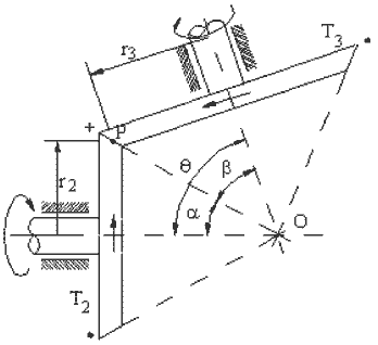
Figure shows two bevel gears in contact, the angle between the axes of the gears being q. It follows that:
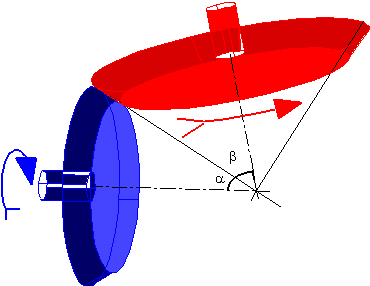
Bevel (Conical) Gears
θ = α + β
and
\displaystyle \frac{{{{\text{ω}}_{{13}}}}}{{{{\text{ω}}_{{12}}}}}=\frac{{{\text{r}_{2}}}}{{{\text{r}_{3}}}}=\frac{{{\text{T}_{2}}}}{{{\text{T}_{3}}}}=\frac{{{{\text{r}}_{2}}/\text{OP}}}{{{{\text{r}}_{3}}/\text{OP}}}=\frac{{\sin \text{α}}}{{\sin \text{β}}}={{\text{R}}_{{23}}}
The direction of rotation must be determined by noting that the velocity of the two cones at the point of contact (P) will be the same. If link 2 is rotating CW when viewed from point O, link 3 will rotate CCW when viewed from point O. A convenient form of determining the direction of rotation of the gears is to consider an arrow representing the direction of rotation for each gear. If the arrow is piercing into the paper, one will see the end of the arrow which will look like a ” +” sign. If it is piercing out of the paper, its tip will be seen and it will look like a “.” sign. In the side view of a gear, the arrow showing the rotation of the gear can be represented by the above two signs. At the point of contact of two gears, the arrow will either pierce into (+) or out of (.) the paper and on the other sides of the gears it will be the opposite. Hence, the direction of rotation of each gear can be determined using this convention.
Example:
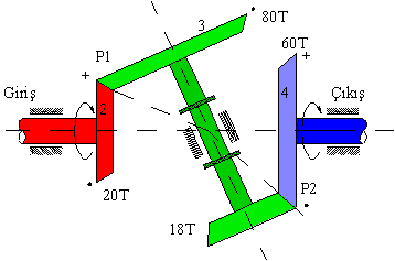
Consider a compound gear train shown. Determine R24 and the direction of rotation of link 4 with respect to link 2.
We have \displaystyle {{\text{R}}_{{23}}}=\frac{{80}}{{20}}=\frac{{{\text{ω}_{{13}}}}}{{{\text{ω}_{{12}}}}} and \displaystyle {{\text{R}}_{{34}}}=\frac{{18}}{{60}}=\frac{{{\text{ω}_{{14}}}}}{{{\text{ω}_{{13}}}}}
or
\displaystyle {{\text{R}}_{{24}}}=\frac{{{\text{ω}_{{14}}}}}{{{\text{ω}_{{12}}}}}=\frac{{20\cdot 18}}{{80\cdot 60}}=\frac{3}{40}=\frac{{\text{Product of driving gear tooth number}}}{{\text{Product of drive gear tooth number}}}
In order to determine the direction of rotation of link 4 relative to link 2, consider link 2 rotating in a certain direction i.e. let us assume clockwise rotation when viewed from the right. The arrow that represents the direction of rotation will pierce into the paper on the top and will pierce out of paper at the bottom of gear 2 as shown. Link 3 will rotate such that at the point of contact it has the same velocity magnitude and direction with link 2 (Point P1). Link 4 will rotate such that at the point of contact it has the same velocity magnitude and direction with link 3 (Point P2). Hence if we place (+) and (.) signs satisfying these requirements, we see that link 4 rotates in the same direction with respect to link 2. Therefore:
\displaystyle {{\text{R}}_{{24}}}=\frac{{{\text{ω}_{{14}}}}}{{{\text{ω}_{{12}}}}}=\frac{{20\cdot 18}}{{80\cdot 60}}=+\frac{3}{40}=+0.075
If bevel gears are used in planetary gear trains, we cannot state the direction of rotation of the planets, since the angular velocities are not additive in spatial motion. However, the gear ratio between the gears that have a fixed axis of rotation can be determined in the manner discussed before.
Example:
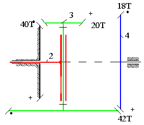
Consider the planetary gear train shown. We can write the gear ratio between links 1 and 4, when the arm (link 2) is considered fixed as:
\displaystyle {{\text{R}}_{{14}}}=\frac{{40\cdot 42}}{{20\cdot 18}}=\frac{14}{3}=\frac{{{{\text{n}}_{{14}}}-{{\text{n}}_{{12}}}}}{{{{\text{n}}_{{11}}}-{{\text{n}}_{{12}}}}}
The sign of the gear ratio is determined with the convention described before (considering the arm as fixed).
Noting n11 = 0, we obtain:
n14 = (1 − 14/3)n12
or
N24 = n14/n12 = −11/3
Where (-) sign states that link 2 (arm) and link 4 rotate in opposite direction relative to each other.
Example:
The gear train shown (schematically) below is known as “Humpage’s bevel gear differential” link 2 is the input and link 4 is the output. We would like to determine the speed ratio N24 Considering the gear train 2, 3 and 1, link 3 is the planet and link 5 is the arm. Hence:
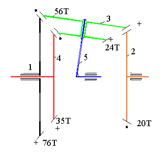
Humpage’s Differential
\displaystyle {{\text{R}}_{12}}=\frac{{{{\text{n}}_{12}}-{{\text{n}}_{15}}}}{{{{\text{n}}_{11}}-{{\text{n}}_{15}}}}=-\frac{{76\cdot 56}}{{56\cdot 20}}=-\frac{19}{5}
Since n11=0 : n15 = (5/24)n12
Considering the gear train 1, 3 and 4, link 3 is the planet and link 5 is the arm. Hence we can also write:
\displaystyle {{\text{R}}_{14}}=\frac{{{{\text{n}}_{14}}-{{\text{n}}_{15}}}}{{{{\text{n}}_{11}}-{{\text{n}}_{15}}}}=+\frac{{76\cdot 24}}{{56\cdot 35}}=+\frac{228}{245}
Since n11=0:
n14 = (1 − 228/245)n15 = (17/245)n15 = (17/1176)n12
or
N24 = n14/n12 = 0.0145.
How does a differential operate?
In all four-wheel vehicles, when taking a turn the outer wheels must travel more than the inner wheels which means these outer wheels must have a higher speed than the inner wheels. Since they are driven by the same engine, if one uses a mechanism of one degree of freedom, different speeds for inner and outer wheels can not be achieved. Hence a mechanism of two degrees of freedom conical planetary gear train which is known as differential is used.
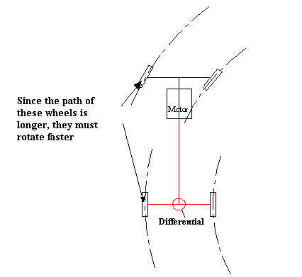
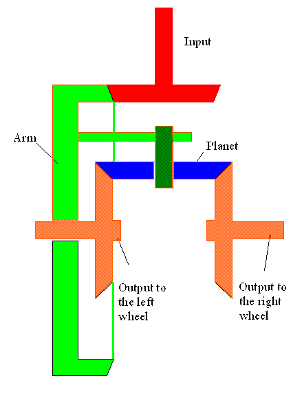
The shaft output of the gear box is the input and rotates the arm. The planet is connected to the arm by a revolute joint(In most cases there are 3 or 4 planet gears) The gears attached to the right and left wheels rotate about the same axis. The system has two degrees of freedom.
If the two wheels are subject to the same load both wheels rotate with the speed of the arm.
If the load acting on one of the wheels is larger than the other, then that wheels stop rotating and the other wheel increases its speed twofold. When taking a turn, since the inner wheel will be subject to a more sliding friction than the outer wheel, the inner wheel will rotate less than the outer wheel.
Since the system has two degrees of freedom but one input, the motion is determined by the external loads acting on the tires. Because of this sometimes cars slip on icy road if one tire is on ice (no load) and the other is on dry ground.
You can see a similar differential in toy cars which change their direction when it hits an obstacle.
South Pointing Chariot (About 2600 BC):
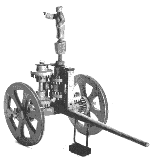
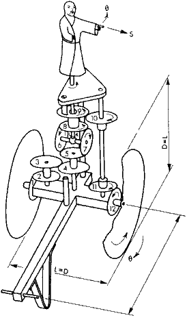
Below is an ox driven cart that was used as a compus by the Chinese when traveling in Gobi desert or in Fogy areas. As can be seen the gear tooth are made of pins. Although the gear technology was not that superior, their knowledge about planetary motion and differential is remarkable. From the relative to the cart the chariot body is rotated opposite to the rotation of the cart so that the chariot always shows the same direction.
If you want to learn more, simply type “south pointing chariot” in any search engine and you can see plenty of explanations.
