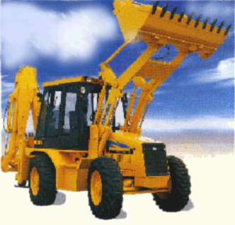
The Photograph shown is the Backhoe-Loader construction machine that you see in most construction sites. At the front there is a loader which loads gravel or the like to a truck and at the back there is back-hoe to dig the ground. You can use different attachments for different tasks for the loader and back-hoe, depending on the application.Our first concern is the loader.

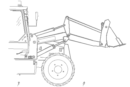
A simplified engineering drawing of the front loader assembly is as shown. Note that a lot of details are neglected.

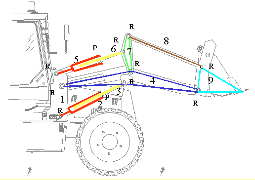
The Schematic kinematic diagram of the mechanism involved for the front loader is as shown. Note that each link in practice may be composed of several different rigid bodies that are rigidly connected to each other.

In this mechanism:
| The number of links: l = 9 |
| The number of joints: j = 11 (9 revolute, 2 prismatic joints between the piston and cylinders) |
| Degree-of-freedom of the joints: fi = 1 (for all joints) |
| Degree-of-freedom of space: λ = 3 (planar motion) |
| Degree-of-freedom of the mechanism: F = 3 (9 – 11 – 1) + 11 |
| F = –9 + 11 |
| F = 2 |
The two degrees of freedom refer to the displacement parameters between the piston and cylinders. Although the joint between the piston and cylinder is a cylindrical joint rather than a prismatic joint, since the rotational freedom is not utilized in this planar mechanism, This joint must be considered as a prismatic joint.The two freedoms are controlled by the hydraulic pressure. One of the freedom is used to lift the load up by rotating the main boom relative to the chassis, the other freedom is used to dump the load by rotating the bucket relative to the boom.