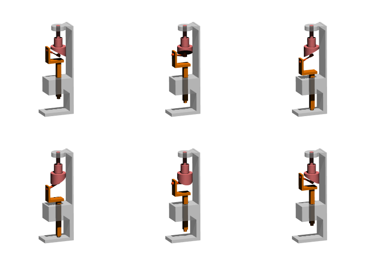
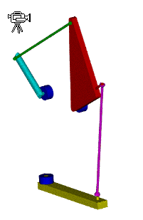
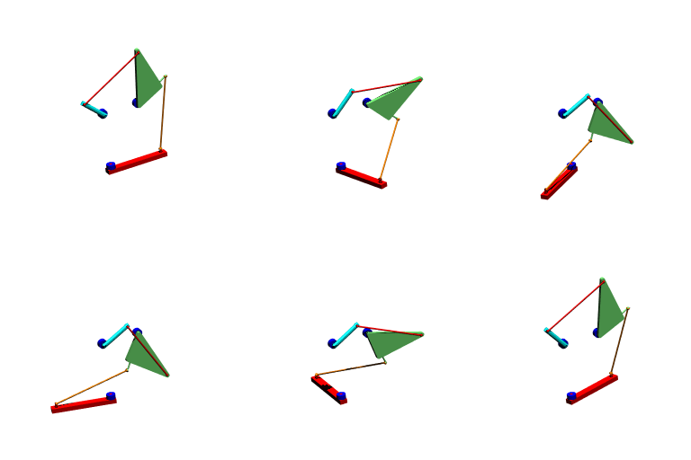
2.1 Degree of freedom of mechanisms-3
As seen from the previous examples, in order to determine the degree-of-freedom of a mecanism one must determine
- The number of links
- The number of joints
- The type of each joint
When determining the number of links one must remember that a link may be composed of several different parts. As long as there is no relative motion between these parts the whole assembly must be considered as one link.
When determining the number of joints and the type of each joint the number of contacts between the two bodies is not important. Remember that there can be only one joint between two links. What is important is the relative motion that is permitted between the two links. The shape of the kinematic elements, the material used is completely unimportant.
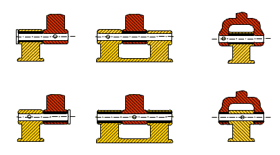
When designing the joints, depending on the application and the available manufacturing facilities, different ways of contact can be used. If the load to be transmitted is of low magnitude, one sided contact may be sufficient and the out-of plane moment created may be negligible. Whereas in case of a mechanism working under heavy load, a symmetric construction where the contact is on both sides may be preferred. Furthernore, the pin can be fixed to one link or can be an integral part of one of the links or can be free.
![]()

To increase the load carrying capacity there can be several contact points between the two links.![]() Each contact point cannot be treated as a different kinematic pair. There can be only one kinematic element between two links.
Each contact point cannot be treated as a different kinematic pair. There can be only one kinematic element between two links.
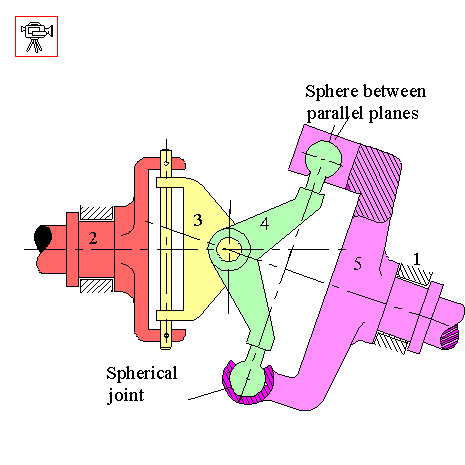
In the above spatial mechanism there are two contacts between links 4 and 5. One contacting pair of kinematic elements (bottom) will permit 3 rotations and no translation, therefore is a spherical joint(f=3); the other contacting pair (the top) will permit three translations and 2 rotations, therefore it is a sphere between parallel planes joint (f=5). However, there can be one joint between two links. Therefore one must look at the relative motion that will be permitted between these two links. First of all, the degree of freedom of this joint will not be greater than the spherical joint (f=3). The contact that forms sphere between parallel planes joint will constrain one of the rotations of the spherical joint. Therefore two rotational freedoms will be permitted between links 4 and 5 which is known as a slotted sphere joint.
A mechanism links may be produced in different shapes depending on the application.
This is a schematic drawing of an in-line slider-crank mechanism:

The figures shown below can all be the slider crank mechanism drawings with the same link lengths but of different link shapes:


In practice depending on the place the mechanism is being used, the material the links are made, the shape of the links, etc. may all change.
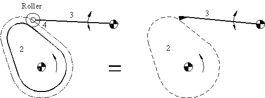
In cam mechanisms instead of a rigid roller at the end of the follower, the roller is free to rotate to reduce the sliding friction. If the degree-of-freedom of this mechanism is evaluated, it has 4 links 3 revolute and 1 cam pair (j = 4, Σfi = 5) and the degree-of-freedom is calculated as (F = 3(4 − 4 − 1) + 5 = 2) 2. Although the motion of the follower requires one parameter (rotation of the cam), 2 degrees-of freedom is correct since the roller is free to rotate about its own axis. In practice, when we are calculating the degree-of-freedom of the cam pairs, we neglect the roller and consider this mechanism as composed of 3 links with 2 revolute and 1 cam pair.
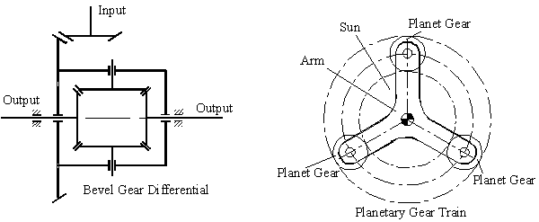
In certain other mechanisms, for better force transmission characteristics, the number of parts that are involved may be increased. A good example is the planetary gear trains. As far as kinematics is concerned, one can omit all but one of the planet gears (These mechanisms can also be considered as mechanisms of critical form, since we require certain dimensional requirements-such as the dimensions of all the planets to be the same, i.e. have the same diameter and tooth number-however, it is not necessary to classify these mechanisms as critical form mechanisms, since by eliminating all but one of the planets we obtain a mechanism that obeys the general degree-of-freedom equation).

The degree-of-freedom equation should not, in general, depend on the link dimensions. There are certain exceptions in which the degree-of-freedom does depend on the link dimensions. These mechanisms are said to be in critical form. We shall call a mechanism to be of permanent critical form if the general degree-of-freedom equation is not obeyed through-out the whole phase of the mechanism motion. These are parallelogram mechanisms (Above figure) or mechanisms that are derived from Robert-Chebyshev theorem. . In the parallelogram mechanism shown above, there are 6 links and , 8 revolute joints, thus the degree-of-freedom obtained from the general degree-of-freedom equation is: F = 3(6 − 8 − 1) + 8 = -1. However, the mechanism is movable due to the parallelogram construction.If the opposite link lengths were not equal, the result obtained from the general degree-of-freedom equation was correct. In planar mechanisms the permanent critical form is usually the result of a parallelogram loop. Below, some examples of the use of this parallelogram mechanism are shown.
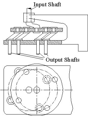
Above example is the multiple drill head, to drill several holes at the same time. This is only possible if the opposite link dimensions are made equal.(If necessary you can increase or decrease the number of drills).
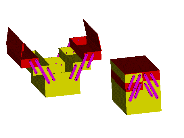
Below, the toolbox shown is a very good example of paralelogram mechanism.

In case of Instantaneous critical form mechanism,the mechanism is movable only for one instant. At some other position, the mechanism is a rigid structure and may be unmovable. In general the degree-of-freedom obtained from the general equation is 0 or negative. However due to the special dimensions, small amount of motion is permitted at the design position. Due to the elasticity of the links and joint clearences the motion is usually of a finite size.
In space mechanisms the permanent critical form is very frequently encountered. The movability of the mechanism is usually achieved by the intersection of the axes of two or more joints at one point. If all the axes of the joints in a space mechanism intersect at one point, these mechanisms are spherical mechanisms and the degree-of- freedom of space must be taken as 3 rather than 6. Some of these permanent critical form mechanisms in space are shown below.
There are lots of different critic form mechanisms in space. In order to determine the degree-of-freedom of such mechanisms, a thorough analysis is necessary.

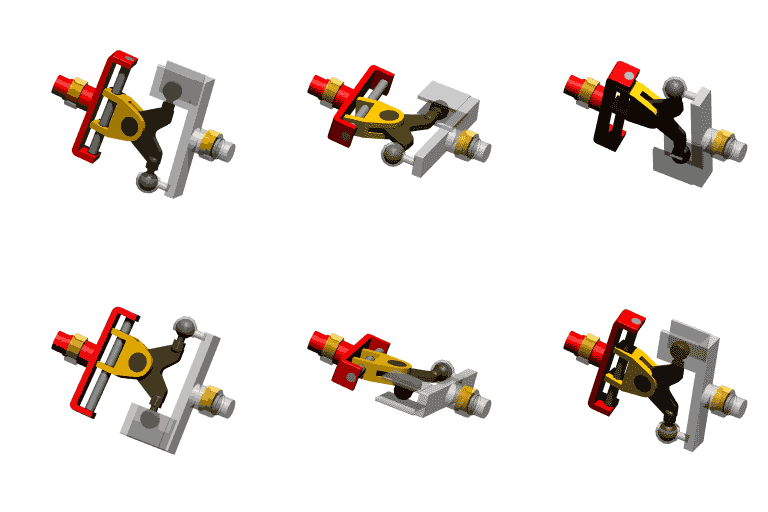
Technical drawing of spatial slide F=1
Solid model and its animation
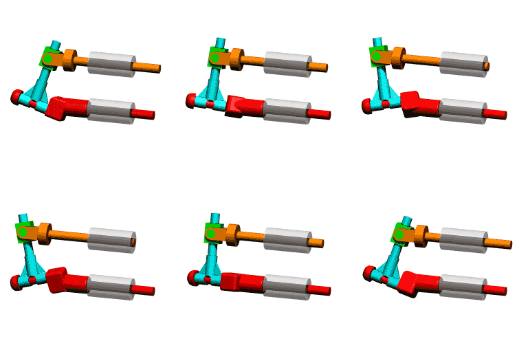
In the above example, the spatial slide will operate only if all the revolute joint axis intersect at one point. Two other similar examples are shown below.

If a planar kinematic chain is formed by sliding and turning joints only, for a constrained motion and for the mechanism to obey the general degree-of-freedom equation the following restrictions must be made:
1. If the kinematic elements of a link form sliding pairs, the axes of the sliding pairs cannot be parallel. In such a case we have a redundant degree-of-freedom, which is the translation of that link about the axes of the sliding pairs.

2. Binary links of the kinematic chain which have only prismatic pair elements cannot be directly connected to each other.

3. No closed link loop may have less than two turning pairs. If there is only one revolute joint, due to the other joints, which will be prismatic, rotation will not be possible between the two links connected by the revolute joint.

4. A three-link loop with revolute and prismatic joints must be counted as one link. An exception to this case is a three link-loop with sliding pairs only.

In the above cases there is either redundant freedom (cases 1 and 2) or immobility (cases 3 and 4)
Another case where the general degree-of-freedom equation cannot be used, or if used will give an incorrect result is the case where the degree-of-freedom of space is not constant for the whole mechanism. For example, consider a spatial four-bar connected in series with a planar four-bar mechanism. The resulting mechanism has 1 degree-of-freedom. But in the general degree-of freedom equation the degree of freedom of space is not clear and neither 3 or 6 degrees-of freedom will not work.
Technical Drawing
Solid Model and Animation
