Example 3

Consider the mechanism that is used as a compressor. The eccentric is rotating at 600 rpm counter clockwise. We assume that the bodies are massless and friction at the revolute joints (except the eccentric) can be neglected. Friction coefficient is μ = 0.1. The p-v diagram of the compressor can be approximated as shown below. At the top dead-centre there is a clearance volume of 0.103*10-3 m3. Both the expansion and the compression intervals are assumed to be adiabatic and governed by the equation pvγ = C where γ = 1.4 (for air) and C is 2.618 and 12.397 for the expansion and compression respectively. The external force acting on link 6 is due to the pressure which is a function of volume. Since the volume is a function of the displacement of link 6, which is in turn a function of the crank displacement, the external force acting on link 6 for each crank position is known. We would like to determine the torque required and the reaction forces at the joints for the whole cycle of the mechanism.

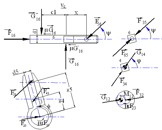
The free-body diagrams of the links are shown in. Since the friction at the revolute joints is neglected, links 4 and 5 are two force members (F35 and F34 are the resultant forces of both the normal joint force and the friction force) Link 2 is a two force and a moment member. Link 3 is a three force and a moment member. One must use the signum functions (σ) which have the values of either -1 or +1 depending on the value of the velocities thus taking care of all the cases possible.
The analytical solution is carried using MathCad and the following equations are written in the form used by Mathcad:
Define the constants

![]()
![]()
![]()
![]()
![]()
![]()
![]()
![]()
![]()

Motion Analysis (Computation for every five degrees):
![]()
![]()
![]()
![]()

![]()

![]()

Velocity analysis


![]()

![]()
Signum functions:
![]()
![]()
![]()
![]()

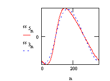
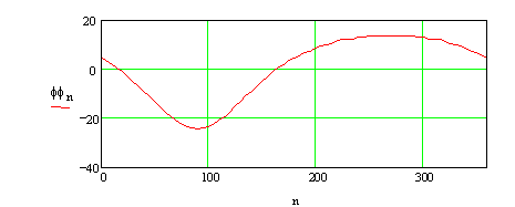
Force Analysis:
External force acting on the link 6 is the force due the compression of the air
Determine the x values at the top and bottom dead-centers.
![]()
![]()
![]()
![]()
which occur when the crank angle is 16° (TDC- point 3 on p-v diagram) and 164° (BDC – point 1 on the p-v diagram). ![]()
![]()
Using pv1.4 = 2.618, when p = 1 MPa, v = 0.103 10-3 m3 and when p = 0.1 MPa, v4 = 5.335 10-4 m3 or Δv = change in volume from TDC = 4.3048 10-4 m3, which corresponds to 38.06 mm displacement of the piston. Therefore at point 4, x = 320.98 mm. Since x70 = 320.109 and x71 = 321.484, we can assume that point 4 is when θ12 ≅ 71°.
Similarly, using pv1.4 = 12.397, when p = 0.1 MPa v=1.62 10-3 m3 and when p = 1 MPa v2=3.1277 10-4 m3 or Δv = change in volume from TDC = 2.0977 10-4 m3 which corresponds to 18.55 mm displacement of the piston. Therefore at point 2, x = 301.465 mm. Since x329 = 301.756 and x330 = 301.077, we can assume that point 2 is when θ12 ≅ 329°.
Using the above results the force acting on link 6 can be determined for every crank angle as:
![]()
 A = 0.111
![]()
![]()
![]()
![]()
![]()

![]()
![]()
![]()

The external force acting on link 6 as a function of crank angle is:

Now, we can determine the joint forces. Angle of the force F56, ψ can be determined from the free-body diagram of link 5:

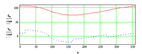
![]()


(Note that G′16 and G″16 are denoted by G121 and G122 respectively.)
The above values are positive if they are in the direction shown on the free-body diagrams.
Check:
![]() This value must be zero
This value must be zero

Solution for F23x, F23y and F43 requires iteration. Initially assume friction is zero:


Now include the friction and assume the value of F23 calculated without friction is correct.

Recalculate F23:


Iterate once more:


Iterate once more:


Iterate again:


![]()
In order to determine whether the solution has converged, let us plot the difference between the last two solutions in terms of percentage:

As can be seen, the difference between the last two iterations can be considered as negligible (the maximum error is less than 0.003% of the magnitude of the force). Therefore, the result is assumed to be sufficiently correct.
![]()
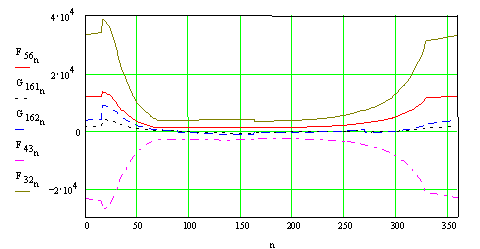
The joint forces can now be plotted as a function of input crank angle:
The input torque required can be determined from the moment equilibrium of link 2:
![]()
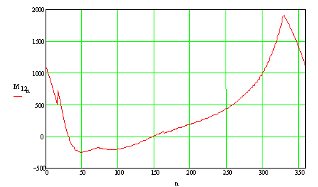
The maximum torque: M12 = 1907 N·m
If friction were neglected (μ = 0) then the input torque required and the joint forces are:

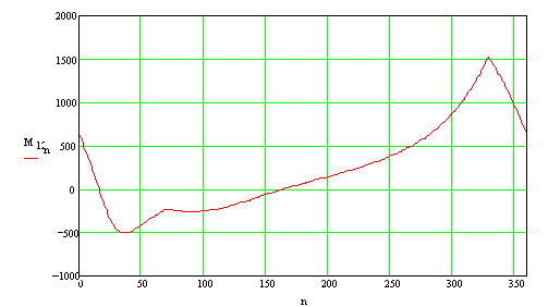
The maximum torque: M12 = 1521 N·m