Categories
CENG795

Ray Tracer Part 3: Multlisampling and Distribution

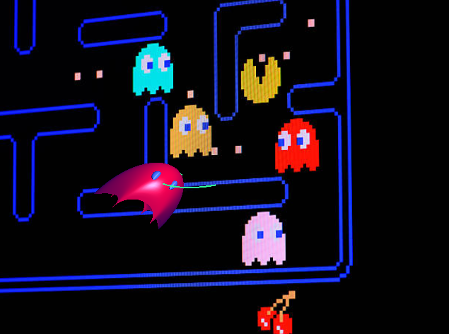
In this part of the raytracing adventure, we are expected to implement multisampling and distribution. Or as I’d like to call it: Accelerated just so we can decelerate. This was a shorter homework with very little issues. Most of the issues were me trying to add unrelated stuff.

Preparations

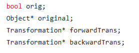
Before everything, I added the new features to my classes and to my parser such as sample number, aperture size, roughness, etc. This part is quite trivial yet starting with this made the progress in the other parts way easier. In the previous homeworks, it was so slow when I had to return to the parser and the classes to add certain attributes to everywhere necessary.

I also created a new class AreaLight which inherits from PointLight and has normal,size, area, u and v vectors as additional attributes. I also now get irradiance and light position from the functions getIrradianceAt and getPos, respectively. This way my original computecolor remains unaffected and during debugging I can easily pinpoint where the problem is.

I also adapted my “drawpixel” function:

for (i=0; i < cam.numSamples; i++)
{
viewing_ray = computeViewingRay(x, y);
colors.push_back(computeColor(viewing_ray, 0, air,
cam.samplesLight[sampleIdxLight[i]]));
}

Color final_color = Filter(colors,cam.samplesPixel);
writeToImage(curr_pixel, final_color);

Sampling

The sampling is done within the camera class. The class initializes samples for pixels, camera, light, gloss and time all in the constructor (Currently it initializes these samples regardless if they are necessary). If there is only one sample, then all are initialized to 0,5.

Random Function: I used std::mt19937 and std::uniform_real_distribution as recommended in the homework pdf.

Sampling Function: I wrote a simple 2D sampling function. I also needed a 1D version for time. In both functions, following sampling types are implemented: Uniform, stratified, n rooks, multi jittered, random. By default I use multi jittered. The code for it is below:

case SamplingType::MULTI_JITTERED:
{
std::vector<int> cols(numSamples);
for (int i = 0; i < numSamples; i++) cols[i] = i;
std::shuffle(cols.begin(), cols.end(),gRanGenC);
std::vector<int> rows(numSamples);
for (int i = 0; i <numSamples; i++) rows[i] = i;
std::shuffle(rows.begin(), rows.end(), gRanGenC);
real spacing = 1.0 / real(numSamples);
for (int i=0; i < numSamples; i++)
samples.push_back({
(rows[i]+getRandom())*spacing,
(cols[i]+getRandom())*spacing});
}

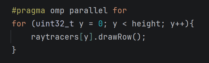
Sampling Application: The application is within the raytracerThread class of course. I hold index vectors with length numSamples for each sample array within the camera, except the aperture samples themselves. I then shuffle all the index vertices for every pixel.

ViewingRay: During the computation of the viewing ray I simply removed the previous 0.5 added to the x and y and replaced it with the x and y’s of the samples.

Filtering

I implemented two types of filters: box and Gaussian. By default, I use Gaussian.

I initially made it so that my standard deviation function would return a colour instead of a float. Yet I then realised summing the elements and returning a float resulted in nicer results.

Initially I thought filter was the easiest and once it worked, it would work flawlessly. Yet throughout my trials for the cases below, I found out that sometimes my standart deviation would be too small and its inverse would be too big (infinity). This resulted in black circles (especially in cornellboxes) in places where colour between samples were not really different. To fix this, I clamped the square of inverse standart deviation to be in [0.1,1.0].
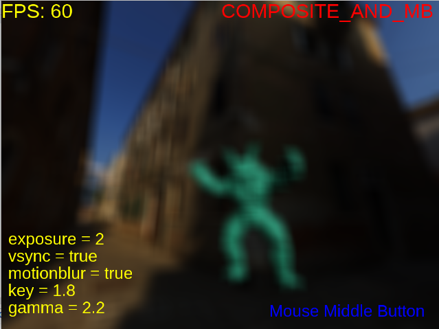
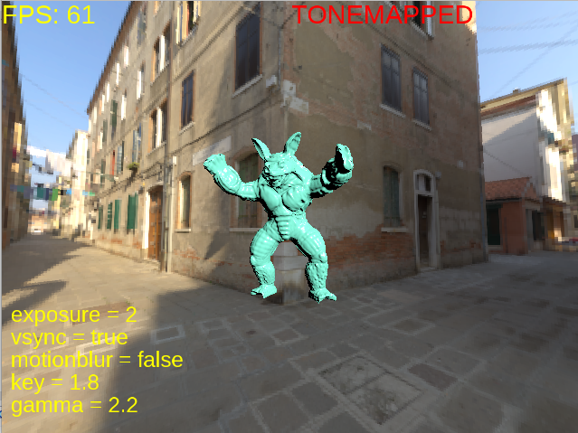
Motion Blur

I’m really glad I started with motion blur because it was easy to implement as a starter.

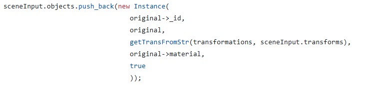
Application of Motion Blur: Every motion blur object is stored as an instance together with a new attribute named motion which is a vector. I also added a has_motion flag in order to quickly check if we should apply motion or not. The application of motion is simple. I did not even change the original intersection and normal functions. Just changed the “getGlobal” and “getLocal” functions that are called by them. These functions now take time as a parameter. Below is an example:

Vertex Instance::getGlobal(Vertex v, real time) const
{
if (has_motion && time > 0)
return (Translate(motion*time)
* (*forwardTrans)*Vec4r(v)).getVertex();
else
return ((*forwardTrans)*Vec4r(v)).getVertex();
}

At first I initialized it very simply, just a “time = getRandom()” line. I then applied the 1D version of various sampling types and it did make the result way less noisy.

Aperture

Then came the aperture. For this, I added a getPos function to the camera class, which returned the original position if it was a pinhole camera. I did not feel the need to add inheritance to the camera yet I might play with this idea later.

After the position was checked, came the manipulation of the viewing ray direction. For this purpose, if the aperture size was bigger than zero, I added these lines:

real tfp=cam.FocusDistance/dot_product(dir,cam.Gaze);
viewing_ray.dir = (cam.Position + dir * tfp)
- viewing_ray.pos;

This was the easiest part that needed the smallest amount of debugging for me. I just initially forgot to multiply by the aperture size while computing the camera position.

Area Light

Now this, this took the longest because I kept misunderstanding the logic. It is funny because while debugging I only had a couple of irradiance computing lines and that was it. Yet I still managed to spend hours debugging.

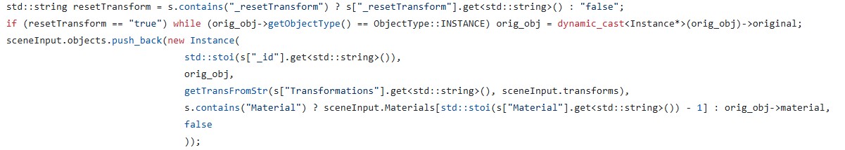
For arealight to work, I wrote a get ONB function first (while reading every step, please assume I did do something wrong and had to debug, it will be too much if I mention it every sentence). I then wrote the get position function. Then came the getIrradiance at function. It was so hard to get this function right. I also realized while separating the irradiance function, I mistakenly added the *cos_theta to this part instead of the actual diffuse and specular terms. This resulted in a brighter scene especially for point lights since for specular term, we do not actually multiply by cos_theta.

I also realised that the reference pictures had two-sided area lights and simply inverted the cos_light if it was negative. Didn’t think much of it.

Also, thanks to the arealight being visible on the cornellbox scene, I managed to see a flaw in my multi jittered sampling function because the light seemed warped and not square.
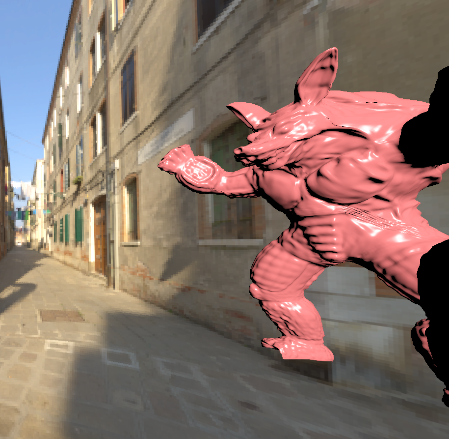
Glossy Surfaces

Oh this was a breeze after area lights. I just used the getONB function and wrote this simple function:

void Ray::shiftRayBy(std::array<real, 2> samples, real roughness)
{
if (roughness != 0.0)
{
std::pair<Vec3r,Vec3r> onb = getONB(dir);
Vec3r u = onb.first;
Vec3r v = onb.second;
dir = dir + ((v*(samples[0]-0.5) + u*(samples[1]-0.5)) *roughness);
}
}

Because no human is without any mistakes, and apparently I’m as human as it gets, of course I managed to do this wrong as well. I initially called the ONB function with respect to the surface normal, not the direction of the ray, i.e. getONB(n). This did not cause any visible issues for meshes but the metallic sphere within the cornellbox seemed obviously off.

Results

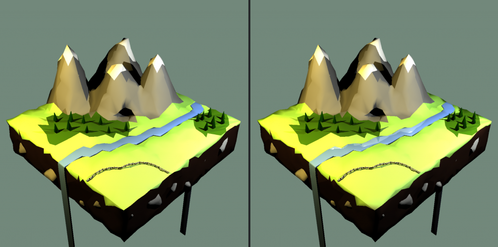
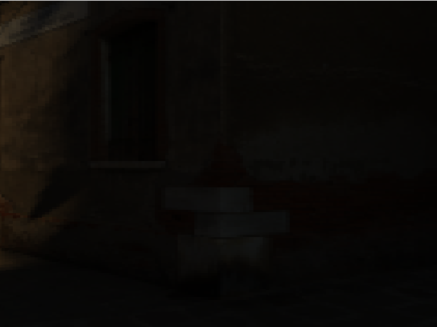
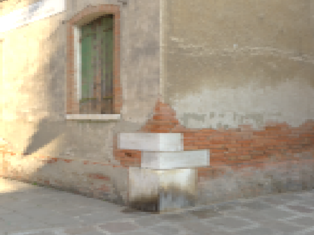
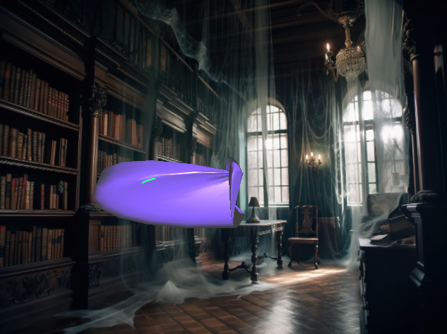
Here is the tap 🙂 I did see some very slight differences in the water but it was so hard to track since the reference was a video. I’m not even sure whether I saw it wrong or not. I tried to turn the mp4 back into frames with the command below but I do not think it replicated it perfectly as there were artifacts and the pngs did not exactly correspond.

ffmpeg -i jsonFiles/hw3/outputs/tap_water/tap.mp4             jsonFiles/hw3/outputs/tap_water/tap_%04d.png
Mine is on the left (The artifacts were more visible when I zoomed more, its hard to see here but it is more blurry)

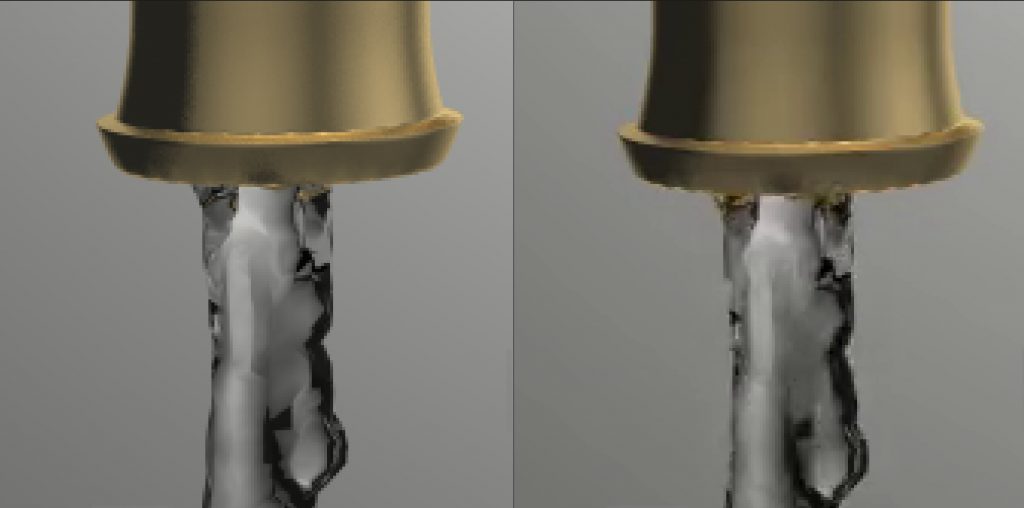
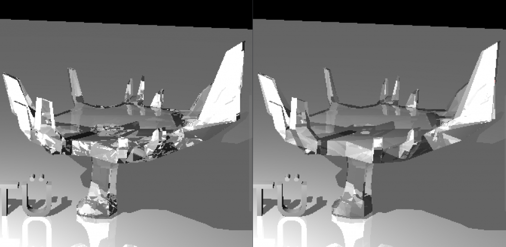
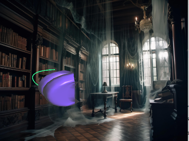
There seems to be slight difference at the mouth of the tap.

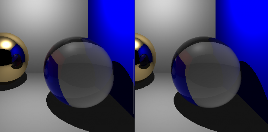
Above is the difference between my glass and the refernece, the one that is blacker in the bottom of the glass is mine.

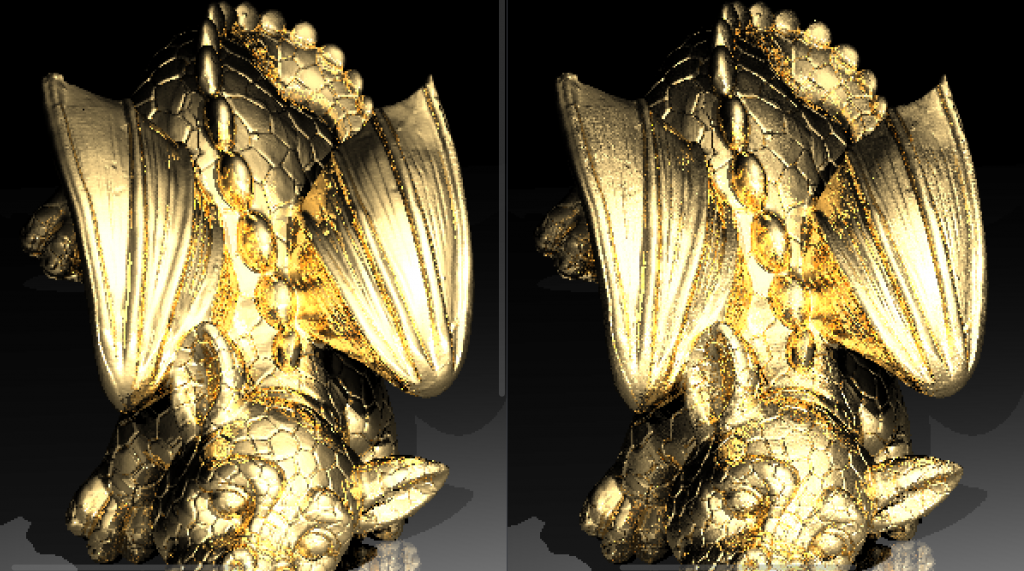
Also, the other dragon also shows some dielectric issues:

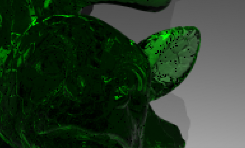
I tried to fix this problem, it is black beacuse of reaching the depth limit but could not really fix it. I am so tired of dielectrics but I guess I still need some debugging for them.

Final Notes

I have a few more things I want to do. First of all sometimes my mesh bvh build takes too long since initially I was working on object bvhes. I want to search for ways to make it faster. Moreover, I need to do a cleanup (as I always do after a submission). Other than that (and my dielectrics) I am currently really content with the way my code is. It is compartmentalized and very easy to develop.

Categories
CENG795

Ray Tracer Part 2: Getting Faster

In this part of the course, the whole point is to make the raytracer faster. I did not do as best as I could, but I realized that while writing this blog. I am also not going too hard on the optimization part to have a structurally sound and modular code, which does take most of my time :’). In total, I implemented bounding boxes, bvh, proper multithreading and back culling. There is also transformations and instancing, which is what I will be talking about first.

M4trix

I started with implementing my own 4×4 matrix and 4×1 vector functions and classes. My M4trix class holds a 4×4 double array and overloads multiple operators as well as having its own determinant, adjugate, inverse, transpose and Identitfy functions. At the beginning I made the mistake of only initializing diagonal values for the identity matrix, which led to me having garbage values for the rest.

I do not hold any 4×1 vectors, instead I create them only for matrix operations.

Transformations

The transformation class inherits from matrix. It has an extra m4trix for normal transform. Its functions are virtual gettransformationtype and virtual inverse.

The other transformation types inherit from transformation and implement the virtual functions.

  • Rotate: axis (ray), angle (float)
  • Translate: x,y,z (all float)
  • Scale: center (vertex), x,y,z (all float)
  • Composite (the one used the most)

For lights and camera, the transformations are directly applied at the parser. For objects, instances are created.

Transformations worked like magic, had no problems there.

Instancing

Instance inherits from object, so has its own get normal, check intersection and get object type functions. It also has a pointer to the original object, pointers to forward and backward transformations.

Both transformations and their normal transformations are computed at the initialization and are Composite by nature. I did not add a differentiation if there is a single type of transformation for the object or not, I precompute the forward and backward transformation together with normal transform matrices either way. The instances can be used for two cases:

  • An object initially defined with transformations:
    • This case is handled because instances can use the original object without transformations, so directly computing the transformed object and storing that requires adding the backward transformation of said object to the transformation of the instance. That is still doable yet the need to add new vertices for this purpose does raise a new memory problem, which is counteractive to the original idea of the instances.
    • For this instances, we create a new object in the heap in constructor and delete it in the destructor. The original object is not within the objects deque. (Objects is now a deque to not have problems with referencing due to one-by-one addition of the instances)
  • Mesh instances:
    • For this case, if it says reset transformation, then the pointer points to the very first original object. If the transformation will not be reset, then the pointer points to that object with that id, regardless if it is an instance or not.

My main trouble was with parsing the instances and putting them into my scene struct. After that was done, since I had no issues with object rendering or transformations, there was no problem left. Also thanks to inheritance and my virtual functions, I did not even change any code in the original raytracerThread class.

Bounding Box

After I handled all the issues for instancing and transformations I then defined a new class: BBox. It has two vertices, vMax and vMin that holds the boundaries of an axis-aligned box, and three functions:

  • Is within: To check if a vertex is within the bounding box.
  • Intersects: To check if a ray intersects with the bounding box
  • Get area: used for surface area heuristics.

I then added a bbox attribute to the object class. And for all intersection checks, it first checks if the ray intersects with the bounding box.

For instances, I automatically had two bounding boxes, one of the original (local) and one of the instance (global). This made local and global bounding box switches at bvh almost automatically.

The class also implements its own get global and get local functions for various structs.

BVH

Now that everything is ready, it is time to get faster. I wrote a BVH class that will create the linear node tree and traverse it. The way I did it is not the most optimized, I have to admit. I put meshes into the nodes. Yet still I got a very big improvement together with bounding boxes. I will continue to improve this part throughout other homeworks but this is how it is currently. Apparently, it is very easy to overlook such things when focused on meeting the deadline.

I had also wanted to try other acceleration structures, yet I did not have time to implement them before the homework deadline.

I did three ways of choosing the pivot: Middle, median and Surface Area Heuristics. As expected, SAH works the most efficient for now. (I later implemented triangle based BVH at the end of this blog to see the time)

I also only included intermediate nodes with two childs. If a node had one child, I recomputed with a new axis. If for all three axes the node still cannot be divided to two and objCount > maxObjCount, I divided it to two at the “start+maxObjCount”th index and continued.

Multithreading

I was already doing multithreading in my previous homework but it was row-based. I added a new function to be able to do it batch-based. My batches are 16×16 unless they exceed image resolution limits.

Now, I also had race conditions when I changed some functions without realizing and started to see black dots on the screen. This was due to my meshes holding the triangle id which they had intersected with when checkIntersection function was called. I thought making the scene constant would prevent such issues, but I forgot I was holding pointers to the meshes. I then fixed it by adding a triangle ID to my hit record and passing it as a parameter to getnormal. I do believe this can be handled better.

Fixing Other Issues

  • Backward Culling: I had implemented backward culling in the previous homework, yet it needed to be improved. I now disable back culling for dielectrics and shadow testing for obvious reasons.
  • Vertex Normal Computation: My code now checks if ply files have vertex normals in them, and if they do, automatically gets them and assumes smooth shading.
  • Dielectrics: In the previous homework, I had issues with my dielectrics, turns out it was due to my very very flawed logic where I forgot to refract the reflections within the dielectric. I fixed that and it works perfectly now 😀
  • Near plane taken as int: In the previous homework I also had a difference between my chinese dragon and the reference png in which my dragon would seem further away than it should be. Turns out I was taking near plane with std::stoi instead of std::stod.
  • Makefile: Since my code got quite big with various files, I extended my makefile to only recompile the updated files. Currently, this does not work as well for me since I hold my configurations as macros in a header and my makefile is unable to update based on macro differences.
  • Logger and Automatic file renderer: Now that we have too many files, there is no way I am giving all that arguments by hand. So I wrote a function to render every json file within a folder as well as a logger that writes the time + total time. It is a simple and quite uneffective logger, embedded within the main raytracer class (this class calls the raytracerthread classes) as I am only interested in logging the time and nothing else.
  • Camera Scaling: For scaling I needed to update near distance by the scaling factor. I realized this after the submission, and I did not update my submission after the deadline so scaling doesn’t work in that code.
  • Deoptimizing the code (?): I did make my code way worse (x3 worse) while trying to optimize it without realizing at one point. I learned that making bounding boxes more complex only makes it worse. I did optimize traversal but currently it does not have any effect since my traversals are quite minor due to mesh based traversal.

Results

I did not put any photos since it is not about the visuals mostly. Besides, my results are currently very close to the references, if not identical. Instead, here is my now public github repository and two videos: github.com/aysucengiz/CENG795

Youtube decided it would be shorts and not a normal video ¯\_(ツ)_/¯

Timings

Okay so just to be able to add it to the blog, I quickly implemented triangle based bvh for each mesh. I did this by adding a bvh to mesh class. I initialized it together with the mesh, and simply called the traverse function. The visuals are unaffected. This is not in the submitted code though, I just was too curious not to put it to the blog. I added the times like the following: (parse time) + (draw time)

Honestly, I did expect it to be very good but this left my jaw open. I was struggling to draw every scene within these past three days.

SceneDraw (old)Draw (no triangle bvh) Draw (yes triangle bvh)
Chinese Dragon0.015s +
21m 56s
1.142s +
11m
3.671s +
0.253s
Car Smooth0.014s +
37.4 s
0.012s +
2.297s
0.037s
0.286s
David0.149s +
5m 15 s
0.273s+
37 s
0.273 s
Ton Roosendaal Smooth0.11s +
6m 1s
0.096s +
50.025s
0.283s +
0.308s
T-rex Smooth2.185 +
3h 48m
1.577s +
1h 11m
10.725s+
0.717s
Other Dragon1.841s +
1h 46m
2.191s +
33 m
8.077s +
0.627s
Lobster1.276s +
+8h
1.264s +
~4h
7.924s +
6.24s

Categories
CENG795

Ray Tracer Part 1: Starting with the Base

This is the first blog post for my CENG795 journey, where I will be coding a ray tracer from scratch and improve it as we learn new things in the class.

Data Structures

I decided to start with defining the data structures. And created a file to include all the minor and major structs except the ones requiring objects which are listed below. I did vectors and vertices two different types to be able to track whether I made a mistake in my computations. For example: Vertex – Vertex = Vec3f. If I somehow got confused and assigned it to a Vertex my code would not compile since I did not override operator – for that case. I am very clumsy so this precausion is needed to prevent annoying mistakes.

Enums: MaterialType (none, normal, mirror, conductor, dielectric), ObjectType (none, triangle, sphere, mesh, plane), ShadingType (none, smooth, flat)

Base types: Color (3 floats), Vec3f (3 floats), Vertex (3 floats), Ray (Vec3f and Vertex)

Complex Types: Cvertex, i.e. composite vertex (id, vertex and normal vector), Camera, PointLight, Material.

Object: Object (abstract class), Triangle, Plane, Mesh, Sphere

The object class has id, and a reference to a material. It also has three virtual functions that are: getObjectType(), checkIntersection(ray, t_min, shadow_test), getNormal(vertex).

Ray Tracer Types: SceneInput and HitRecord.

I will talk about parallel computing later, however SceneInput is the constant struct that is read by all the threads and never written on once a scene is parsed. It contains all the information within the json file, and the objects in a single objects vector. It also stores some precomputed values that are common for every thread.

Every object type has their vertices as references to the Complex Vertices vector of SceneInput. This was initially fine as I first initialized the vertices vector then the objects in my parser. However, became a problem with the ply files as I later added new vertices to my vector and when the vector got too big, it reallocated. I solved this by turning the Vertices vector into a deque. This was not an issue as I only use the vertices from within the objects and not directly from the list.

Hit record is as it sounds, holds the necessary information when our ray intersects with (or hits) an object. It includes an intersection point, a normal and an object pointer. I also added a mesh pointer just in case. Because when a mesh intersects with an object I only hold the triangle which does hold the necessary information from its mesh, so holding the mesh and the triangle separately is usually not needed.

For all these types, I overrode the necessary operators and the << operator. I also added: clamp, exponent(Color), dot product, determinant, magnitude, normalize, isWhite.

File Management

This is the section where I talk about my parser, which will be short since the data structures section talks about most of it. I will also write slightly about writing the result to the file.

Parser: I wrote parser as a namespace instead of an actual class. Its only used function from outside is parseScene, name self explanatory. In this function we first get the json data from file (using nlohmann json), then get small information such as background color and max recursion depth. If these are not given in the file they are initialized to their default values. Then the cameras, the lights, materials, vertices and objects are written to the sceneInput struct. For meshes using ply files, I read the files using happly library and add the new vertices. I also check for degenerate triangles and handle lookat cameras and vertex orientation (all given as “xyz” for our cases). For materials, if everything is given as 0 value, I set the type of that material to none and skip objects with material as “none”.

Writing the result: I initially used the function given last year to us for the raytracer, which worked for small scenes but was unable to write very big chunks of data. I then made it so that the ppm file format was P6 instead of P3, and wrote using fwrite which worked seamlessly. However, as it was recommended in the homework pdf, I wrote another function using the stb library, which worked as well.

Ray Tracer

For the main ray tracer, I have two classes: RayTracer and RayTracerThread.

The RayTracer is the class initialized by the main function and holds the scene information. It has the functions parseScene(input_path), drawScene(camID) and drawAllScenes(). The user should first call parseScene function, then draw scene.

ParseScene simply clears the vectors in the scene, calls parsers parseScene and sets the number of cameras, objects and lights.

DrawScene first initializes some common values in scene. After this step, the scene is information is never modified until another draw or parse scene function is called. I first create the list of raytracers made up of RaytracerThreads and then call them parallel.

The RaytracerThread is where the magic happens. It holds references to the camera and the scene which are both marked as constant. It also holds a static int to count the number of done threads. I sometimes printed this to see how long was left for especially complex scenes. The computeColor function is the main function of this class. It first checks for max recursion depth, if the depth has not been reached, then it checks for object intersection. If an object has been hit, then does reflection if it is a mirror or a conductor, does refraction if it is a dielectric. We then check for shadows and if the point does not fall under a shadow its color is written.

The only part I could not solve was the dielectrics, I am doing something wrong I assume but could not find it until the due date.

Mine are the ones on the right. It is more obvious with the science tree where I lack some details, I believe especially the reflections within the dielectric have some problems.

Moreover, with the other dragon scene mine turned out to have a slightly “dirtier” look. (Again, on the right). I could only render this once since it takes too long, therefore I could not test on it. And I believe since easier scenes are not as detailed I was not able to catch the difference. But I was not able to catch any other significant difference in other scenes. (I guess it is the difference between smooth and flat shading)

Mine is on the right, the river has reflections
Mine is on the right, it has reflections. The materials are not listed as mirrors but they have mirror reflectance so I don’t know if I am doing something wrong.

I have reached my space quota so I cannot add the other pictures. Most of the scenes seem the same except some additions such as mirrors. The berserker has slight shading differences. For some reason my chinese dragon seems further away than it should be. I added the two as pictures to a drive folder: https://drive.google.com/drive/folders/1xIVvd5WrOO7IWe1ksRcW1p_JNYF945gA?usp=sharing

I did not see any significant difference in the other scenes 🙂

Tests & Times

Below are the times of the scenes with and without backface culling. I also implemented a logging feature for this reason, but it was not in the submitted homework so I will be talking about it in the next part.

Both cases were done while my computer was in the same state as much as possible. I also run my raytracer via WSL 2.

NameParsing Timew/o Cullingw/ Culling
Science Tree0.003s4.32s1.77s
Science Tree Glass0.007s9.46s5.53s
Bunny0.006s3.11s1.15s
Bunny w/ plane0.008s39.03s27.8s
Chinese Dragon0.783s32m 16s21m 56s
Low Poly Scene Smooth0.015s24.72s17.31s
Tower Smooth0.012s22.83s18.89s
Car Smooth0.014s53.2s37.4s
David0.149s7m 51s5m 15s
Raven0.011s36.21s24.1s
Utah Teapot0.051s2m 16s1m 37s
Other Dragon1.841s2h 28m1h 46m
Ton Roosendaal Smooth0.11s7m 12s6m 1s
T-rex Smooth2.185s5h 0m3h 48m

The lobster took longer than expected so I do not have a w/ culling version of it, it took more than 8 hours.

Categories
CENG469

Meteor Simulator

Hello, this is the blog for my project of CENG469, where I attempted to make a meteor simulator. It is not perfect and does lack enhancing featured I wished to have, but I had so much fun I think I will continue to finish and make it prettier.

Here are the master features that I implemented all:

  • Procedural terrain generation with Perlin Noise (with tesselation shaders): Done
  • Procedural meteor generation: Done
  • Permanent land deformation with the crash: Done, though not perfect
  • Selection of where the meteor will land: Done, could be better
  • Particle, light and camera shake as crash effects: Done, though particle effects are laughable
  • Realistic shading: Done

For the extra features, I did want to have a night day cycle, however I hardly found a space skybox, let alone a skybox with sun and atmosphere so that was scrapped.

I did do my implementation with a meteor shower in mind since you can call multiple meteors at the same time without a problem. But currently the only way to have a meteor shower is to click frantically.

I am quite content with my noise functions, though I only used perlin noise with different random functions or combinations.

Part 1: The Surface

I implemented this project over the second homework, as I thought I could use various aspects of it, especially the hdr part. This did not go as planned as I hardly found a skybox at the very end. To get back on track, I am just warning for text and cubemap artifacts from the second homework.

I started with drawing a grid with vertices and then applied 2D perlin noise on top of it. At the beginning, without normal calculations, this is how the ground looked.

Quite majestic, looks like waves. But that is not the aim so I calculated the normals as follows:

I first took four points, each one slightly to the left,right,forward, and backward. Then I applied the noise and found their final location, then computed the final normal by subtracting the points in the same directions and taking the cross product. Here is the code:

The result is quite great… For now. I then changed the implementation to use tessellation shaders and after that this is how it looked from above:

I fixed this issue by not precomputing the corners since when x and z are multiplied by 2 in the perlin noise functions, they could exceed the precomputed corners.

After fixing it, I continued to play with the noise function to have it the way I wanted. I also added dynamic tessellation, though I did not use it because my computer could hardly handle the smallest acceptable tessellation size.

Part 2: The Meteor

After handling the surface, I thought the meteors would be the same. It was not. There were a lot of design questions as well as the 3D Perlin noise. When the noise was 3D I was not able to do the small tricks I did during the render of the surface. Handling the normals, the noise function and everything took longer than the surface. I again first implemented without tessellation shaders to be sure.

I used a simple sphere algorithm (https://www.songho.ca/opengl/gl_sphere.html) that mostly separates the sphere into patches, just like we want for tessellation. But as seen in the picture, the top parts need to be single triangles, and thus not four cornered patches. I did not completely fix this, just made it really small.

This is the initial meteor surface, I then lowered the resolution and the perlin noise degree. As you can see in the top left corner, even though I was not making any computation with the cpu, my poor pc was struggling as my GPU is just decent. To help my pc, I used dynamic tessellation and lowered the size drastically when the meteor is slightly far. It did help quite a lot.

Part 3: The Crash

Adding velocity etc. was simple. The main idea was how would the crash look like. I chose to have a very big sphere that is far away, as that is the easiest way to mimic a crater. After doing that (and struggling with embedding the meteor just right), I realized the crater was so smooth. So I did it again, I applied Perlin noise. It’s like magic.

Part 4: The Effects

Then came the effects. I applied a randomize shake, a flickering light and a very sad particle effect.

For those, you can check the final demo.

Part 5: User Interaction

Arrow keys: Movement around the “map”. To do this I simply move the modeling matrix in the opposite direction because the cubemap and the camera needs to stay the same.

N/M: Go down/up

Scroll up/down: Change FOV

Left click: Call a meteor to crash if the dot in the middle is crossing the surface.

The other control are the same as homework two.

Final Result

In the end, I managed to get a decent FPS by managing the tessellation and sizes of everything. It could be better, since I did not utilize compute shaders.

I chose this project to be like this because I wanted to get comfortable with OpenGL and I managed to do just that. There is more to it of course, but right now I am very comfortable with shaders and passing buffers, as I was not after the homeworks 🙂

Categories
CENG469

Particle Simulation

Designing the Structure

Before everything, I started with deciding the structure I would use to code. I took the previous homework’s code as a base and deleted everything but the bare bones. Then started adding homework requirements to the code. I decided on using the following arrays:

  • gParticles: xy – coordinates, z – age
  • gVelocity: xy – current velocity, zw – initial velocity
  • gAttractors: xy – location, z – mass

I then wrote the functions regarding adding and removing attractors. I used a simple array logic where I hold the number of attractors as an integer and every attractor in the list with index bigger than number of attractor – 1 is not included in the velocity computation.

Compute Shader

After handling the initial requirements, I then moved on to the compute shader part. First of all, I changed the version to 4.3 since that was when the compute shaders were introduced.

For this part I mainly used the compute shader slides as a guide. However I did need to make some changes to make it work fully.

Initially I made the simple mistake of having two different buffers for the particles for both compute and vertex shaders. This did not work since the vertex shader is supposed to get the particles with the updated vertices. I did not pass the velocity or the attractor buffers to the vertex and fragment shaders since all I needed was the age and the positions for these shaders.

At this point I was still seeing nothing on the screen, I later found out the reason was 2 things:

  • Depth: I was choosing the depth as 1.0, which was the deepest.
  • Projection matrix: Naively, I thought I did not need it since we were working on 2D. I was suspicious as to how that would work and eventually decided on adding back the matrices but did figure out viewpoint and modeling matrices were unnecessary. The need to update the projection matrix at the reshape function gave a hint about its importance. I did a small researched and found out that I would need to make it orthographic, not projection.

After these changes, I started seeing something. This was the halfway point of my overall effort. For me, the process before seeing anything is always the hardest since there can be too many problems causing the black screen.

First Particles On Screen

By default, I chose the origin as the middle of the screen. Since the code for nearly everything was ready and needed debugging, this view is actually all the points on top of each other. Also, at this point I was initializing my projection matrix to have (0,0) right in the middle, thinking it would make it easier. I later made it from 0 to gWidth as that turned out to be easier for debugging.

I then tried to slide my origin to the side. And achieved the picture below instead. This very obviously shows a memory alignment issue.

It was a simple problem, I had started to use a 4 member struct instead of 3 and thought I had changed it everywhere, but had forgotten

After changing that, every particle was on top of each other regardless of the origin. This meant I could start playing with the velocity computations. Initially, just adding the velocity meant nothing, it would still seem as a single point. To fix that, I initialized the age of the particles with 1.0 and decremented with their index until zero. I got the result below (I was also testing the delta time variable here).

This raised a question in my mind, wouldn’t it be too line-like if I did everything the same for the points except the ages? To prevent this I initialized every point with a randomized velocity vector and passed this initial velocity to the compute shader so that when a particle reaches the end of its lifespan, it will not loose the randomness.

Adding Attractors

I then started fixing the attractors, this was the point I changed the projection matrix back to a more usual choice, where (0,0) is at the top left. I added an attractor by default at (0,0).

Please ignore the red block, the text rendering was broken

Seems like everything (except text) was working, right? That was until I decided adding new attractors. Turns out I was magically expecting the compute shader to get the updated attractors array even if I only initialized the buffer once with an allocated and then deleted array and never touched it again. Needless to say I changed that and could start to add attractors. As default, I added four attractors to the points:

Slight randomization makes the initial view less box-like

Keyboard and Mouse

A slight tangent to mention the key bindings:

  • Q: Closes the window
  • W: Increases delta time
  • S: Decreases delta time
  • T: Toggles text
  • R: Stops/starts particle movement
  • G: Changes mouse mode
  • V: toggles vsync
  • F: Makes the window fullscreen (This was working a bit weird at the ineks, it would turn the whole monitor into a blackscreen for a while.)
  • Mouse left button: adds a new attractor with the mass value on the screen to the clicked position or changes the origin to the clicked position.
  • Mouse right button: Removes an attractor.
  • Mouse scroll: Increases or decreases the to-be-added attractor’s mass

Particle Motion

This was the fun part. Before this, I added one+one blending to make the final result appealing. Initially dividing the velocity with dot(dist,dist) would result in a weird movement so for a while I had removed it. For a while I also had no limits for the delta time so the interesting visuals below were formed:

I then decided to use sqrt(dot(dist,dist)) and everything looked way more smooth, it was like a magical touch.

Particle Count vs FPS

I have an intel GPU.

Particle CountFPS (w/o vysnc)
10^34900
10^44400
10^51900
10^6220
10^722

Final Result

One thing I did not do was to make the resizing keep the proportions of the window, i.e. if the origin is at the middle it should still be in the middle of the window after the resize. This is not the case currently, the placements of the points do not change, they just wander to a bigger area. Video (sorry for the lack of video quality):

Categories
CENG469

Deferred Lighting

Hello! This is the blog for my deferred lighting homework. The homework mainly includes: cubemaps, hdr and tone mapping, deferred lighting, motion blur. This blog will not be in order of how I did things as I preferred to explain things in a cleaner order.

Cubemap and HDR

I started with the cubemap by writing a cubemap.obj file. I changed the 2d texture arrangements to 3d cubemap. This part was mostly seamless.

Initially, I did sigmoidal compression only to be able to see better. In this part, I also added the exposure and gamma correction variables.

Mouse Movement

I then moved on with the mouse movement. At first I tried to do it with two quaternions one for the right vector and one for the up vector. However, this did not feel like a first person camera at all, so I then replaced up vector with y-axis. This felt way more smooth. Though it did introduce a problem, if the user looks towards exactly 90 degrees up, the gaze vector shifts abruptly. This could be solved by limiting the gaze slightly but I did not have time left for that so that abrupt change is still present.

Adding Armadillo

Adding armadillo without the deferred lighting was the easiest. In this part I arranged its location and the light location itself to make sure it was in a proper place where I could see. I did not choose to have one light, I actually thought about doing more after I was done with everything, but I was never done with everything.

Initial armadillo w/o deferred rendering
I tried to match my light with the sun in the cubemap

Texts and FPS

I then moved on to the text. I had some trouble making them visible on the screen because I forgot to bind its texture and had some blending issues. The below picture shows when I was unable to show the text properly, I then fixed it by enabling blending before writing my texts onto the screen.

For the fps, I initially recalculated it for every frame I would render. But that would make it flicker between 59 and 60 a lot so I then limited it to change each second.

Deferred Lighting

I died a little bit here. Though I followed both the video and the documentation for deferred shading, for a long while I could not render anthing properly. My quad just would not show anything and I could only see something when I rendered the quad as armadillo which is below.

I was so confused because I was doing everything in the tutorials and this took me around two days to figure out. I even rewrote the code for deferred rendering from scratch (which made my code in the end way clearer so I’m glad).

It was such a minor mistake, I was rendering my quad wrong. Originally, I was trying to render it like a face of the cubemap. But then I checked how the renderQuad function in opengl tutorials were coded and implemented that. Worked like a charm, I was on the verge of tears. Everything else was already ready so I could directly get the position and normals look.

Keyboard and Window

I then implemented some more minor things such as the key bindings and the window resizing. To fix the placements of the text, I called the function that calculates the perspective in the reshape function. I did not fix the aspect ratio to 1 so that the visuals would not stretch as shown in the picture below.

For the keyboard the buttons are as follows:

  • Q: close window
  • R: Toggle rotation
  • G: toggle gamma correction
  • V: toggle vsync
  • space: toggle fullscreen
  • +/up: increase exposure (I did not have a numpad)
  • -/down: decrease exposure
  • 0: TONEMAPPED
  • 1: CUBE_ONLY
  • 2: MODEL_WORLD_POS
  • 3: MODEL_WORLD_NOR
  • 4: DEFERRED_LIGHTING
  • 5: COMPOSITE
  • 6: COMPOSITE_AND_MB

Composite and Motion Blur

For motion blur, I took the function in the slides and arranged it so that it would blend the whole screen regardless of depth. I initially thought I would make it more optimized, but ran out of time and could not. Doing the motion blur itself was not challenging, but handling the composite structure that would do the blurring was. At first I tried to do it without an extra buffer, then gave up and added the buffer. For a while I swam in blits, clears, depths, enables and disables and buffers. I really should learn to first learn then implement because that would be way easier, but then again I cannot learn anything without implementing.

The final structure that worked for me:

  • Geometry pass on gbuffer
  • Arranging blending ( by making armadillo’s alphas 1.0)
  • Lighting pass on gBlurbuffer (used for both blurring and tone mapping)
  • Rendering cubemap on gBlurbuffer
  • Tone mapping and motion blur on default buffer

I then wrote the blur function to the final shader and only enabled it if blursize is bigger then 0. I found blursize by simply finding the manhattan distance between the past cursor point and the present and limited it to be maximum 20 (otherwise my poor laptop would freeze). The motion blur is not the best, though it would be very easy to make it more efficient with the code at hand, I just need to change how blurSize changes.

Tone Mapping

After handling motion blur, the base for the tone mapping was already ready. I initially tried to calculate the average log luminance manually by bringing the texture to cpu and multiplying. This reduced the fps greatly, so then I did what the pdf recommended. I created a mipmap for the texture I used with gBlurbuffer and calculated the average log luminance with the 1×1 mipmap. I love giving myself heart attacks so I forgot to give the key value as a uniform but instead wrote it as “in” and could not see anything at first.

Final

I fixed the floats and booleans in text because they were bothering me, added the pressed keys to the screen.

I learned a lot of things, even when I thought I had understood everything. It took longer than I expected but ended nicely.

I still did not download any application for screen recording , so here are some screenshots.

What is missing?

  • The abrupt change of gaze when we look up 90 degrees up.
  • Resize is not smooth (on my computer), though when I tried it on inek it was smooth but I did nothing to make it so.
  • Motionblur is not based on time but based on how many frames it will take for it to diminish. Not the best look in my opinion.
  • The armadillo started to get cropped after I implemented diffused rendering.
  • This is the most trivial one but texts are not aligned dynamically, so the writing for tonemapped just seems floating in air.
  • I was a bit confused about in which mode I was expected to do gamma correction, so now I just apply it in the TONEMAPPED mode.
Categories
CENG469

Flying Blinky

Hi there! This is my process of designing a ghost that roams in a room by implementing Bezier surface and curves. My progression was not linear for either of the parts and I jumped between them, and my pictures show that.

I used the template given by the instructors which helped quite a lot.

Part 1: the Model

I started with the design of the model. The first idea was to have a model that looks like the generic ghost (as a flying white cloth), but I somehow needed to make it a closed model, which meant I had to close the bottom. I also wanted the edges at the bottom to be spiky.

First design: Simple

I really liked my first design, but it made things too easy. It had only two surfaces and there were no surfaces needing C1 continuity. I wanted to learn both how to make the normals work at triangles that shares edges with other surfaces, and to ensure C1 continuity.

Second design: Jellyfish

This design was the final version while I was designing at MATLAB. It is possible to see that it is not C1 continuous. I explain my process to fix that further into this part.

To show the model on OpenGL, I first defined the control points. To have a easily modifiable definition, I used macros and constant variables:

This way I ensured cleaner and less confusing looking surface arrays.

I then determined the vertices the triangles which will be formed with using bernstein polynomials with n=3.

Since my model was simple, for the duplicate vertices I found the ones which would overlap and did not add the duplicates to the vertex array. To make this process simpler, I used a [surface_count][sample_size][sample_size] sized vertice index array and stored the indices there to be used for the tesselation.

During tesselation, I directly used the index values from the vertice index array, this worked seamless. I then drew the faces with glDrawElements.

Initially, I did not add the normals. You can see it below, the surface seems flat.

Model On OPenGL: Single surface with no normals.

My first idea to find normals was to add 1/6 the normal of the every face to the vertices. However, this is not a fool-proof way as there is no guarantee that a vertex would share 6 faces all the time. The solution was easy: To add the normal for the every surface and then to normalize.

To add multiple surfaces, I used a different vao for each, yet same modeling matrices for all. This way all the surfaces would move at the same time.

After seeing every surface on screen, I could see a very obvious mistake, the shapes were nothing like what I had designed.

Model on OpenGL 2: Multiple surfaces wrong vertex function

The problem was before tesselation, while determining the vertices. I was looping from i=0 to i<3 instead of i<4, a very simple yet hard to catch mistake. After that, it started to look a lot more like my model. However, the discontinuity was way more obvious. I could make it less by changing the variables I had defined earlier but could not get rid of it entirely.

Model on OpenGL 3: Nearly correct vertex function, before C1 continuity.

Then I realized that my model by design prevented C1 discontinuity. Initially, I was very confused as to why the top was arching even though the control points were colinear there.

Initial
Higher middle arch

So I tried to increase the height of the middle arch, this did looked ok at MATLAB, but the flaw was still very obvious at OpenGL. I later realized the control points at the bottom were not colinear, in fact they were far away from being colinear. This meant I could not have a nice arch on the sides, but sacrifices were made and I made them colinear. This indeed solved my continuity problem.

Then, I was faced with another issue. This was very obvious and easy to fix. I realized I was summing the normals even at the very sharp edges and decided to keep the duplicate vertices at the sharp edges.

Fixed C1 continuity
Duplicate vertices at sharp edges

At the end, my model was finally presentable. But I wanted it to have at least a resemblance of a face, so I needed eyes.

For the eyes, I added two same surfaces without modeling on MATLAB ( I drew by hand). They are elliptic tubes. I defined new shaders for them since I wanted them to be a different colour than the ghost. I changed their diffuse coefficient to choose their colour as my liking. For testing purposes, white was easiest to see errors.

I, again had to fix the duplicate vertices by hand since I did not write an automatic code for it. Thanks to my vertice index array, such requirements are easy to add and just needs a small if condition.

Duplicate vertices present
After eliminating duplicate vertices

Then I put the eyes back into their sockets 🙂 I also slightly tilted the eyes to better fit the shape of the ghost.

Final version of the model

Part 2: Curve

For the curve, there were several steps I needed to do.

First, I needed to determine the control points. I preferred to randomize them completely for the model to stay within the window boundaries. However at first, it was far from randomization, so I determined certain ranges. The curve now would be within any box I determined.

I liked the idea that the ghost would come quite close to the camera, but this meant that I needed to restrict x and y ranges quite drastically. I did not want to give up on any range of the coordinates, so I did the modification below:

This works because my z values are always smaller than -1.

After the control points, I again sampled several vertices on the curve using the same Bernstein polynomials. Initially I chose 10 as the sample size, which was not smooth at all.

Curve: Small sample (before adding the ranges to the randomize function)

Then I increased it to 100, which allowed for the ghost to travel quite fast with a very smooth movement.

The curve also needed to be static and not move together with the ghost. For this purpose, I separated the model and the curve’s modeling matrices and made sure the curve modeling matrix never changed after initialization.

Since the curve needed to be green, I defined new shaders for the curves and set the diffuse reflection to green. I also did not like how thin the curve was, so arranged the width to be 2.0. This then caused the wireframe object (when wireframe is enabled) to have bold lines as well, so I made the width to its original value, 1.0 before rendering the wireframe object.

Part 3: Movement

First, the ghost needed to follow the path. I simply updated its coordinate to the next vertex in the curve by keeping a global path index. When the path index was at the end, I regenerated the curve with C1 continuity as below:

Everytime I regenerated the curve, I found the vertices on the path and set the path index to 0. This also required an update at the vertex buffer.

Then, the ghost needed to keep doing the roll movement while looking towards the way it is going. I defined an up vector, which is initialized to (0,1,0), and a gaze vector which is,

I then found the u from the cross product of direction and up, and recalculated up by taking the cross product of the new u and direction. This sometimes causes the ghost to turn upside down, but there are no abrupt orientation changes.

I put the created orthogonal basis into a matrix and put right before the final translation matrix which translates the ghost to the position of the current curve vertex, and right after the 90 degree turn function (which I had to add because apparently I designed my model sideways). I fixed the pitch rotation to none and left the roll quaternion rotation in the sample code.

At last, I had to put the curve to its center. Why? Because if I did not, then when it needed to rotate to look at the direction, it would rotate around an imaginary origin. I changed the translation matrix and lowered every index in the original 16 control points of the every surface.

Part 4: Keyboard Input

Wireframe: When the user presses W, the model is shown as wireframe. I defined a “wireframe” flag which controls if the drawing function calls the object solid or wireframe.

Show path: The path disappears/reappers when P is pressed. Again, I defined a flag that determines if glDrawArray for the curve is being called or not.

Stop moving: When space is pressed the ghost stops/starts moving. The code skips every update function if the corresponding flag is not set.

Finalizing

At the end, I looked at my model, and saw pac-man ghosts. If I had started with this intention, I definitely would make it look more like them. After this realization, I changed its colour to a more reddish colour to make it look like the red ghost, Blinky. Its eyes are now blue to match the ghosts. Moreover, I added a 3D-ish pac-man background and made the ambient lighting blue to match the atmosphere.

Final: Solid with curve
Final: Wireframe without curve

This was a very fun process, where I had to learn to incorporate:

  • Bezier curves and surfaces with Bernstein polynomials
  • Tesselation
  • Both C1 and just C0 continuous surfaces
  • A moving and a static object in the same scene
  • Moving along a path
  • Using quaternions and rotation matrices