Hey everyone! I wanted to share my experience working on my computer graphics homework, where I implemented Bezier curves and surfaces. It was a fun but sometimes frustrating journey.
Starting with Bezier Curves
First, I took the given 2D Bezier Curve MATLAB program and extended it to 3D. I wrote a function to generate Bezier curve points and checked the results in Octave. The results were nice and acceptable for the homework. So, I decided to generate random Bezier curves within the scene limits with some basic tweaks. For simplicity, I used the Bezier curve equation instead of matrix calculations. I could not understand why but the matrix representation resulted in mislocated start and end points although the curves were legit Bezier curves.
Shaders and Visualization
I used separate vertex and fragment shaders for the curves:
- Vertex shader: Just position coordinates.
- Fragment shader: Only color (no shading, since that was enough for me).
I drew the curve and control points to figure out a good sampling frequency and length.
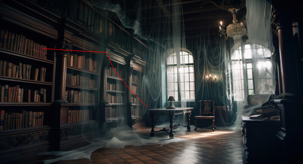

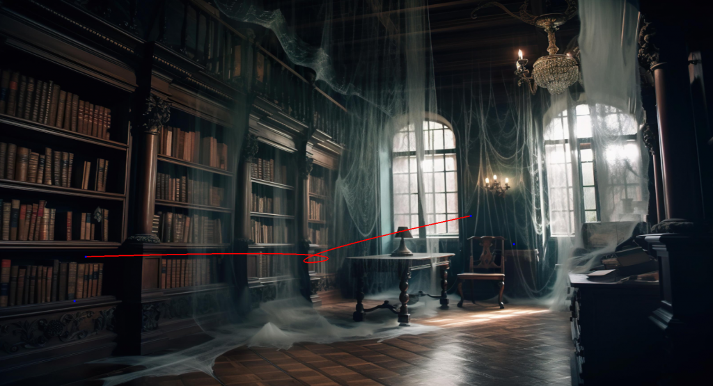
Then, I created a point and moved it along the curve.
Later, I increased the speed and added more random curves for the point to follow.
At this point I realized that somehow I need to dictate that the curves are long enough to be visually pleasant by paying attention to the constraints:
- Min/max values based on the scene.
- C1 continuity (so the curves connect smoothly).
I also drew the tangent of the curve to visualize it. I calculated the tangent by subtracting the last point from the current point (With a little trick for the first point of course).
Moving the Bunny
Next, I replaced the green point with the given bunny object. I removed all pitch and roll movements at first.
- Used
(0, 1, 0)as the initial up vector. - Used the current tangent as the gaze vector.
- Created a basis for the tangent and transformed the bunny into this basis.
The problem I encountered at this point was the alignment of the object because there was not a middle or center point of the object. To solve this problem I calculated the middle point by taking average of edge coordinates (highest and lowest etc) and changed the transition matrix based on the object. It worked for the bunny but I knew that this was not a good solution. However I decided to create my object by knowing the center point instead of trying to generate an algorithm or rules for the center point.
Adding Roll Motion
I introduced a quaternion to make the bunny roll 45 degrees back and forth. I reordered the transformations:
- Scaling
- Rotating
- Rolling
- Translation
This looked better. Here the initial up vector is looking down. At this stage I did not realize this mistake. But towards the end of the homework I solved the issue. It was related to the vector calculations.
Problems I Noticed at This Stage
- Fully random curves sometimes looked weird. The control point generator needed tuning.
- The object’s movement speed and rolling speed needed adjustment for smoother motion.
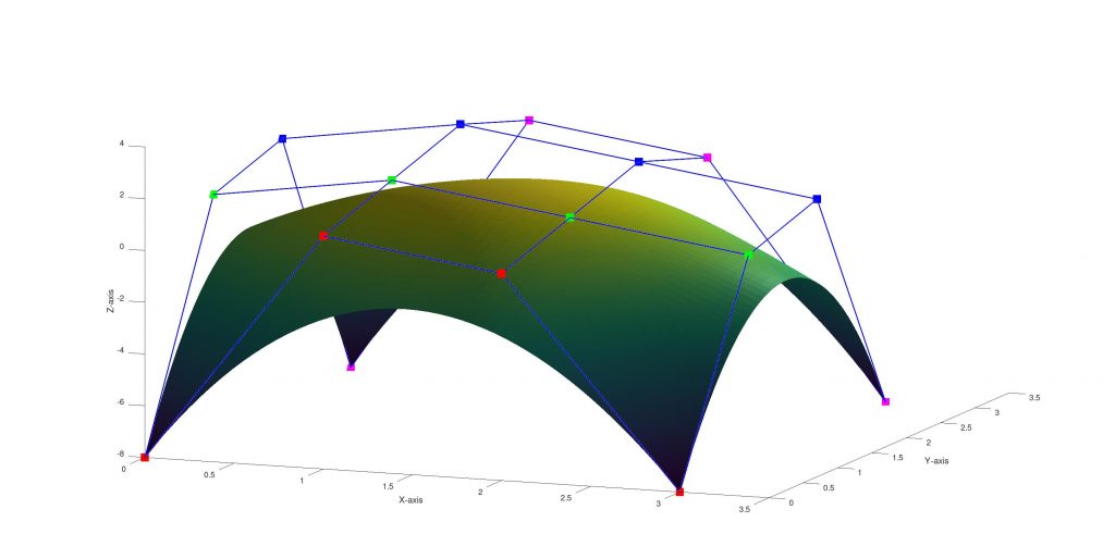
Moving to Bezier Surfaces
I wrote an Octave script to visualize Bezier surfaces. I colored points differently to make design easier.
Half-Sphere Example
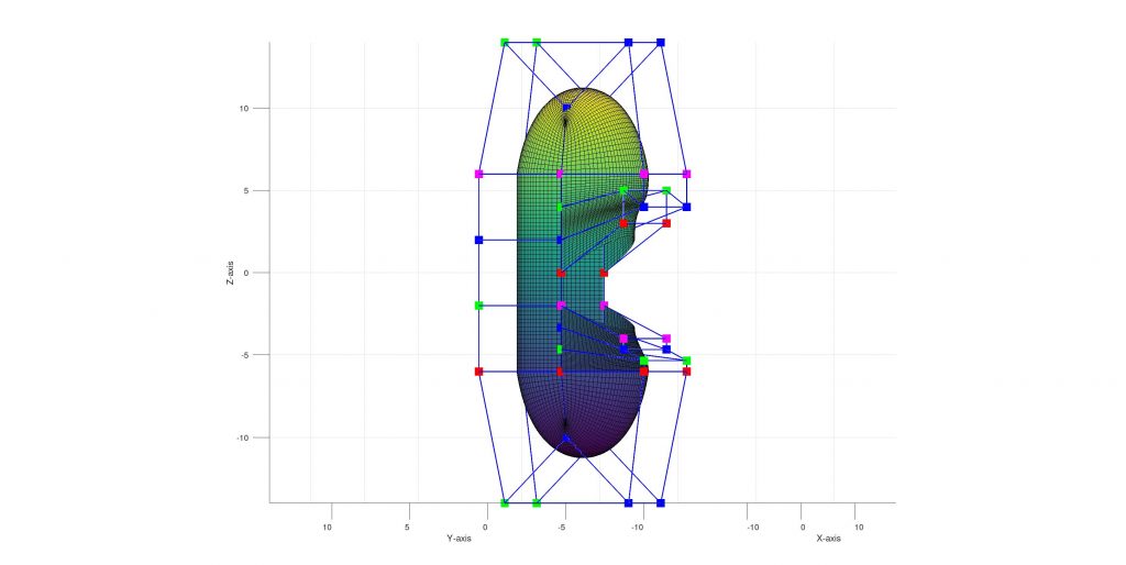
I created a customizable half-sphere-like Bezier surface generator with Octave. With the code half sphere like Bezier surfaces can be generated by defining the center point and some parameters based on the center point ( which I defined by experimenting with them and which I can not interpret exactly what they are doing 🙃.)
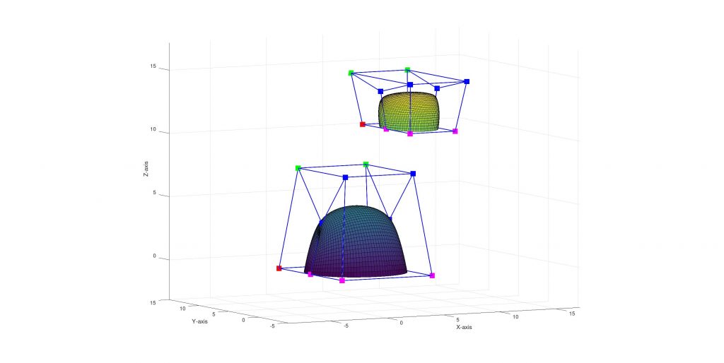
The Octave code:
function [P] = bezierHalfConvex(r, s, u, k, b)
    P = { [r 0 0], [r r*s 0], [-r r*s 0], [-r 0 0]; ...
           [(r*u) 0 b], [(r*u) (r*s*u) k], [(-r*u) (r*s*u) k], [(-r*u) 0 b]; ...
           [(r*u) 0 b], [(r*u) -(r*s*u) k], [(-r*u) -(r*s*u) k], [(-r*u) 0 b]; ...
           [r 0 0], [r -r*s 0], [-r -r*s 0], [-r 0 0]
        };
end
I also wrote Octave functions to rotate and translate the surfaces. All Octave codes are uploaded with the homework.
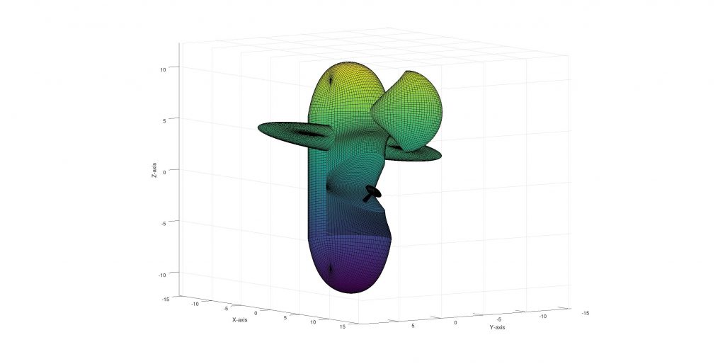
Creating the Moving Object
With the Bezier surface calculator, half sphere generator, rotation, translation codes in my hand, I started to create an object by using Bezier Surfaces. The definitions can be found in bezierScript.m file. I tried to draw something like this:

This is what I could before getting bored by point calculations.
🍽️ Ingredients are:
- 2 Bezier half convexes (I used my script for all half convexes) for the front and back of the plane.
- 1 half cylinder for base of the plane
- 2 half cylinder like shapes for the sitting area, current shape:
- 1 to close sitting area completely
- 2 for wings
- 1 for the wing like shape on the upper back of the plane, up to now:
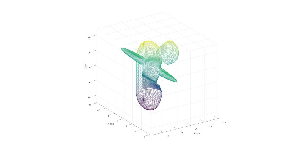
Adding some cosmetics:
- 1 half convex for the steering wheel shaft
- 2 half convex for the sterring wheel, the end result:
Moving to C++
I transferred the points to C++ by simply outputting the calculated points from Octave script and:
- Generated 30 Bezier curves.
- Used those points to create a 30×30 resolution Bezier surface.
- Calculated indices using a simple triangle method (3 vertices per triangle → 1682 * 3 indices).
- Calculated the normals by averaging the triangle normals. However, I made a mistake at this point. I realized it too late, and I had already spent a lot of time on the homework. My normal calculations are not fully appropriate for the homework specification, since I calculated them using only the current surface. Because of how I structured the code (I kept the surfaces isolated from each other), fixing this would be a laborious task. I thought about manually selecting adjacent surfaces and writing loops for those, but that feels tiring and like an ugly solution. Another option is merging the surfaces and storing them as a whole, and recalculating the normals, but that would require a good amount of refactor. So, I sadly decided to skip this requirement.
Exporting and Rendering
- Exported the generated object to an OBJ file to use the existing code for obj files.
- Adapted rotation, scale, and translation matrices to put the object on the curve correctly.
Problems and Fixes
- Upside-Down Object
- There was a mistake in the up vector calculation. It was upside down. I corrected the mistake by simply changing the sign.
- Incorrect Normals
- Some surfaces were facing the wrong way which causes them to be ignored because of the back face culling.
- Quick fix: Reversed the order of Bezier curves in the points data.
Assigning the Key Presses
- Space: Pauses movement.
- P: Stops drawing the curve and curve related things (the tangent vector, up vector etc.)
- W: Enables wireframe mode (I had to modify the shader).
After pressing Space and P:

After pressing Space + P + W:
Last-Minute Changes
The homework required the Bezier surface resolution (s and t) to be parametric. I initially thought they were separate but realized they were the same. Instead of reverting, I just set both to the same value. So now both of them are customizable but the program takes one argument for them.
Final Thoughts
It was a long but rewarding homework! There are still some imperfections, but I learned a lot. You can see a resolution vs fps table at the end.
Bezier Surface Resolution vs FPS Table
My monitor is 144hz. There is a performance problem about wireframe mode when resolution is high (Up to 96 there is no problem). I do not know the reason. To enable wireframe mode I am
- Changing glPolygonMode from “fill” to “line”
- Adding an if condition into the vertex shader
| Resolution | Frame per Second |
| 3×3 | 144 (constant) |
| 6×6 | 144 (constant) |
| 12×12 | 144 (constant) |
| 24×24 | 144 (constant) |
| 48×48 | 144 (constant) |
| 96×96 | 144 (constant) |
| 200×200 | 144 (constant) (But in the wireframe mode it fluctuates between 70 and 90) |
| 400×400 | 144 (constant) wireframe: 26-27 |
| 800×800 | 64-65 (stable) wireframe: 7 (constant 🥲) |
| 1600×1600 | 18-19 (stable) wireframe: 2 |