Engine Project
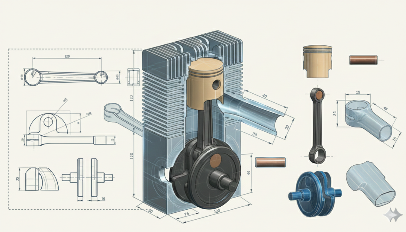
This project involves the conceptual CAD design of a single-cylinder two-stroke engine, developed as a multi-component mechanical system with a focus on manufacturability, assembly, and dimensional consistency.
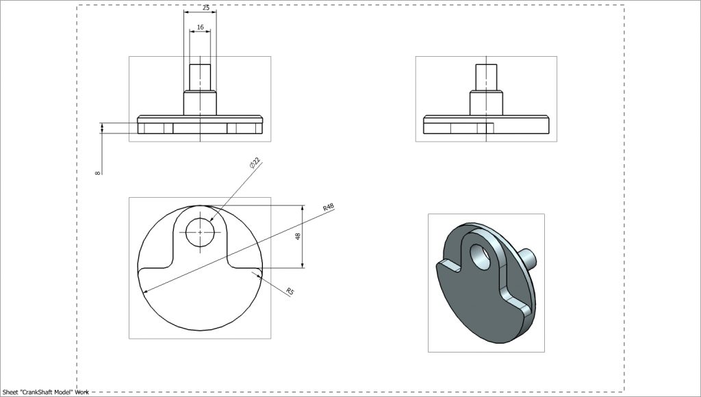
Crankshaft
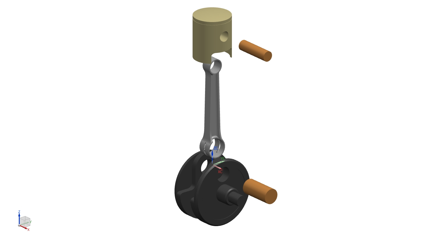
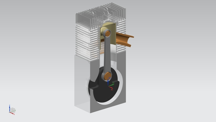
The crankshaft assembly was designed to match the engine stroke and connecting rod geometry, forming the core of the engine’s rotating system. The crankshaft geometry was established based on the 54.5 mm stroke and integrated with the 120 mm connecting rod to ensure proper piston motion and alignment within the engine layout.
The assembly includes the crank webs, main journals, crank pin, connecting rod, piston, and wrist pin. During modeling, clearances and alignment between the rotating and reciprocating parts were considered to ensure proper motion within the engine layout.
Connecting Rod
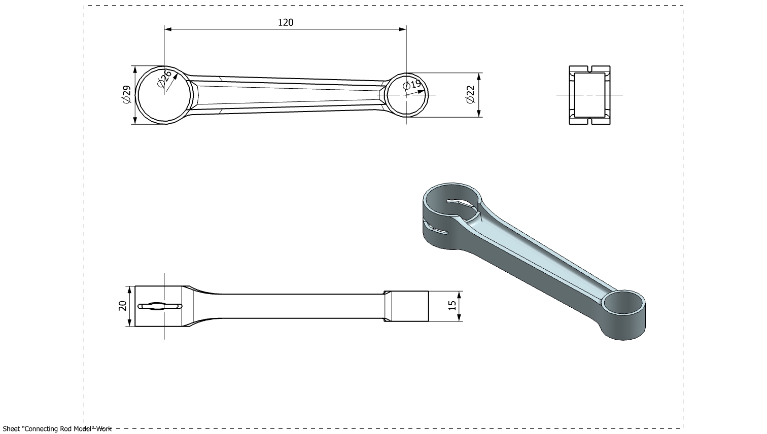
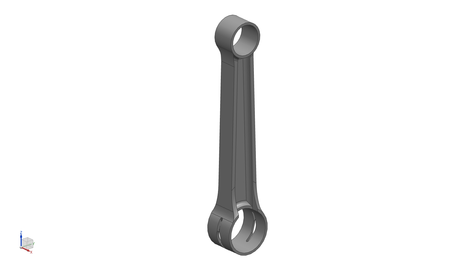
The connecting rod was designed as part of the engine’s rotating assembly to link the piston and crankshaft. A center-to-center length of 120 mm was selected. The big-end bore was sized to accommodate the 26mm radius crank pin, while the small-end bore was selected as 22mm radius for the wrist pin connection to the piston.
These dimensions were defined to ensure proper fit within the crankshaft assembly, adequate clearance during rotation, and compatibility with the surrounding engine components at the assembly level.
Piston Model
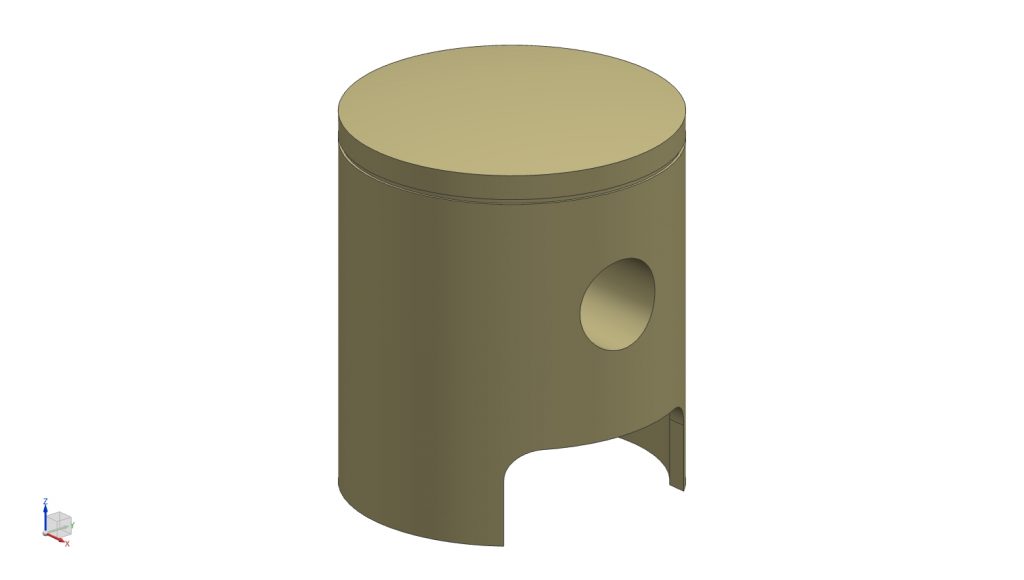
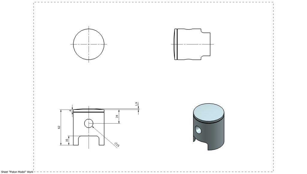
The piston was designed to match the defined cylinder geometry and crankshaft assembly within the engine layout. The model was developed for a 54 mm cylinder bore and incorporates a nominal piston-to-cylinder wall clearance of 0.04 mm to ensure proper fit and smooth motion within the cylinder.
The wrist pin bore was positioned relative to the crown to achieve the intended compression height, with a pin diameter of 15 mm chosen to match the connecting rod small-end interface. The pin axis location was carefully set to maintain alignment throughout the stroke and ensure compatibility with the 120 mm connecting rod length.
The lower skirt geometry was designed to provide adequate guidance within the cylinder while minimizing unnecessary material. Cutouts at the skirt were introduced to allow clearance for crankshaft rotation and internal engine components during operation.
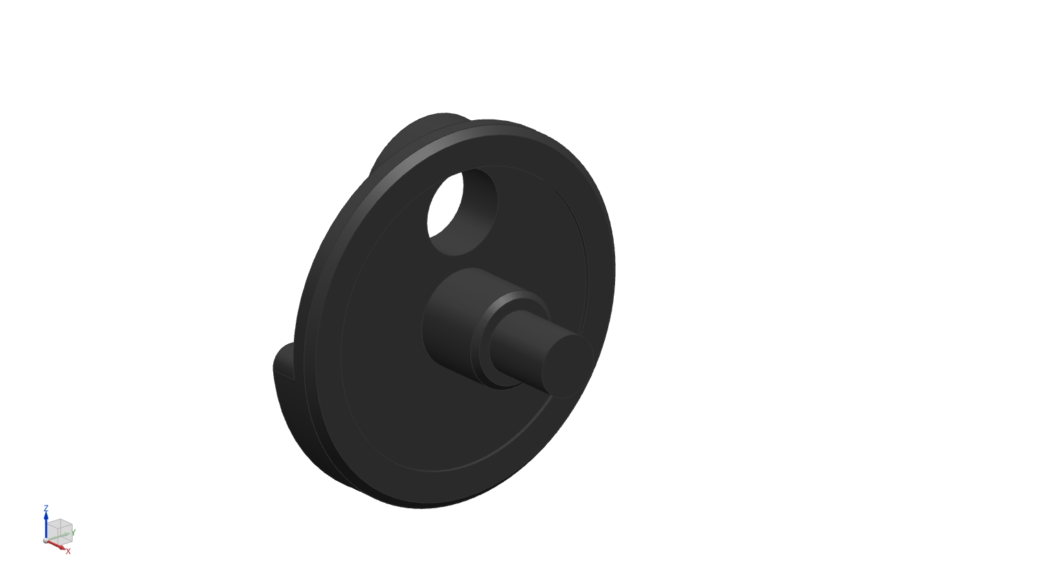
Crankshaft Web
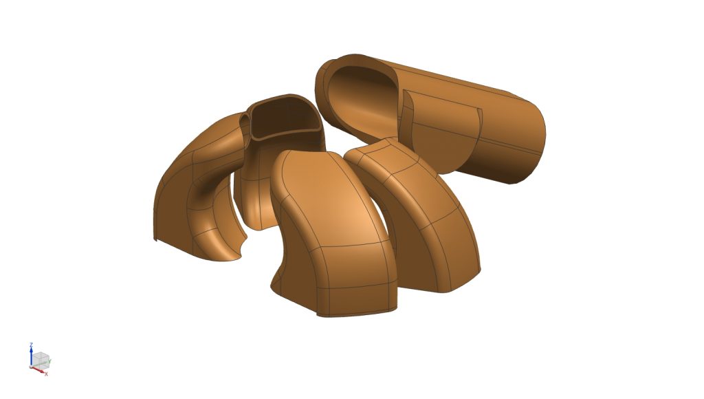
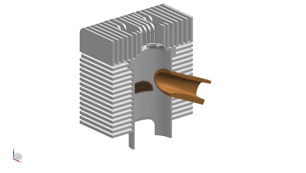
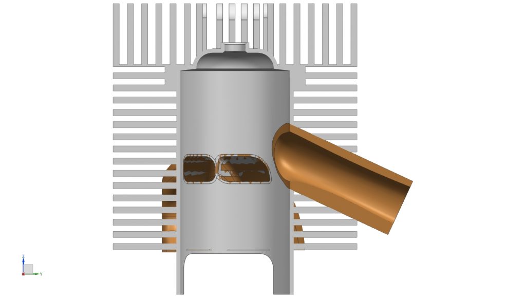
Exhaust and Transfer Ducts
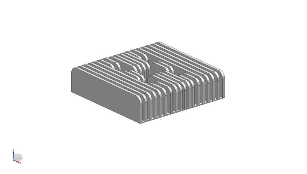
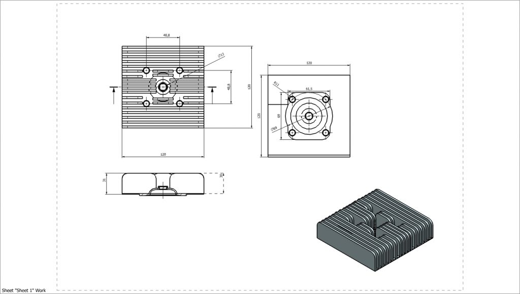
Cylinder Head