Hi, welcome to my blogpost detailing my journey through completing the Surface Rendering HW1 of CENG469. The requirements of the homework was to write an OpenGL program, based on the supplied starter code, that renders terrain based on height data found in .dted files.
Setup
I started by running the starter code. While running commands to start it worked, I wanted to be able run it by clicking a button on VSC. For this purpose, I raided the folder of the last CENG477 homework, which had working launch.json and tasks.json files. Additionally I needed to symlink glad from ext/glad/include into the src directory so that clangd could read the header. With enviornment setup done and starter code working, I moved on to trying to make something I make show up on the screen instead of the default triangle.
Mesh
I reread the lecture slides to find all the code neccessary to create a vao and copied them over into the program. For the vertecies I iterated over the dted height data and created a vertex at each index with x being the first axis, y the height and z the second axis. Next I needded to somehow connect these vertecies to create triangles. After some doodling, I came up with this symmetrical scheme:
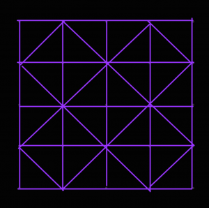
To implement it, I made a second pass and I created 4 triangles around every vertex where (x + y) % 2 == 0 by connecting it with 2 of its cardinal neighbors at a time in counter clockwise direction. This meant the triangle indecies wouldn’t be in order for triangles that are next to each other, but I figured it would be fine. For normals, recalling the slide that mentioned how for some tesselation ratios B-Spline normals might not match triangle normals, and considering that I did not have splines yet, I opted to calculate the face normals of each face in the face pass and add them to the normal data of their vertecies. Finally in a third pass I normalized the normals.
Controls
This seemingly worked, but I couldn’t see the enitrety of the model so to make sure it was right I needed to be able to move the camera. I proceeded to once again plunder 477 HW3’s code to copy over the callbacks and extra variables added to the GLState struct. The keyboard callback code works by checking if the key is a movement key, and if so sets the appropriate bit in the state.moveButtons variable. This variable is then used during main loop to modify the position vector of the camera, which worked fine in this homework. The mouse code on the other hand, was modifying rotationX and rotationY parameters based on the distance mouse travelled and these veriables were being used to calculate the gaze vector towards a (real or imaginary) planet. Not only would would this not work, but it didn’t use quats netiher.
So I started experimenting with quats. I stored a rotation quat in GLState that I could manipulate by multiplying with rotation caused by mouse events and q/e buttons. When it came to using it, I tried to multiply it with something or another to be able to pass it as gaze into glm::lookAt function but it didn’t work. I checked the slides to see if there was a better way and ended up going back to basics by using glm::mat4_cast to convert it to a rotation transformation matrix that I could multiply with the translation matrix, bypassing glm::lookAt altogether.
I could now control the camera, however it didn’t feel right. When I moved the screen 90° down, 90° right and 90° up everything would be sideways. This annoyed me so I decided to add an option to lock the up direction. While trying to make rotation work I had noticed the glm::quatLookAt function that took an up vector as argument. I multiplied the forward vector glm::vec3(0, 0, -1) with my quat and passed it alongside the up vector glm::vec3(0, 1, 0), hoping some magic would fix the up direction. Instead, any attempt at rotating the camera caused it to shake uncontrollably. Upon closer inspection, the camera seemed to be jumping between two positions seperated in yaw by the camera’s pitch angle. I had no idea what caused this, but I decided if it jumps between two spots, applying glm::quatLookAt twice at a time would make it end up in the same spot, which it did! But now the camera couldn’t be pitched and rolls made it very upset. I fixed this by using the new up direction as the up vector in the second call and after limiting the rotation so it couldn’t align with world up, I had a nicely behaved camera. I assigned the toggle for this camera mode to ‘u‘.
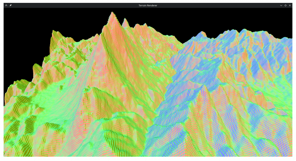
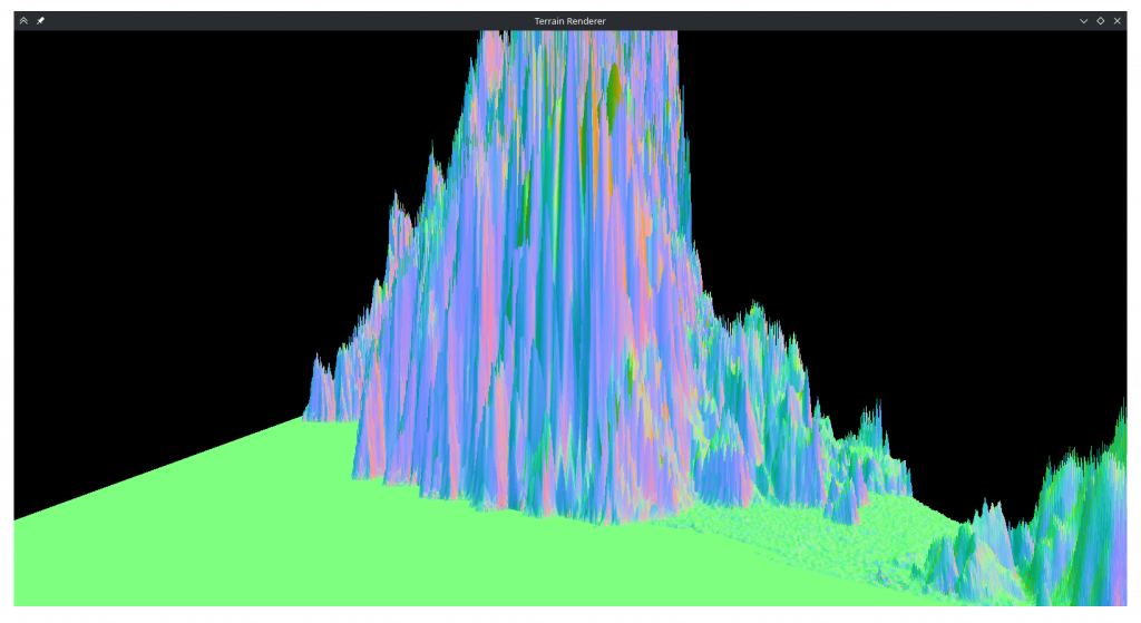
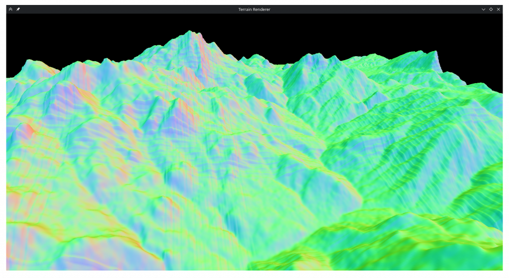
I added the ‘-‘ / ‘+‘ based height controls. I uncommented the shader line that corrects normals, but I liked the “topological map” look uncorrected normals had when height factor is 0 so I added an exception for that. I also added some additional camera controls for going up, down, faster and slower to make getting close to the geometry easier:
| Up | space |
| Down | c or ctrl |
| Fast movement | left_shift |
| Speed up movement | wheel_up |
| Speed down movement | wheel_down |
Tesselation
Next in line was to add spline tesselation. I had already structured my code such that the mesh generator depended on a callback for height data, so I just needed to swap the dted height data with splines and add a sample rate parameter.
The spline equation Q(s,t) = S· involves taking the transpose of a row vector, which didn’t work as glm apparently doesn’t differentiate between row and column vectors. It turns out in glm even though multiplying a matrix with a vector (or vice versa) does dot product-like matrix multiplication, multiplying two vectors does piecewise multiplication. This meant I could to use M·Z·MT·TTglm::dot when multiplying either vector and I would get a float. I added new hotkeys ‘h‘ to toggle sampling between original geometry / splines and ‘j‘ / ‘k‘ to control the spline sample rate.
Around this point I realized that MeshGL wasn’t just a struct that held a couple numbers but it also enforced things that I didn’t understand that limited how it could be constructed or copied. I couldn’t figure out the right way to use it so I lobotomized it and added the code to delete old buffers myself.
This (seemingly) worked but it was very slow to start or change the sample rate. I realized that the middle of the spline equation M·Z·MT did not depend on the sample position, so I could precompute all splines and just access them while sampling. This somewhat helped with changing the sample rate but the program was still slow to start. I decided to use the thread library supplied with the homework to speed it up even more. Using threads to speed up the spline computation was easy enough. For mesh generation after splitting the second pass into face pass and normal pass 1, the vertex and normal calculations could also be parallelized. But if I tried to paralelize the face generation it would scramble the geomety badly. I had to find a way to calculate the face number from the vertex instead of just incrementing it after each face. After more doodling, I found the equation and after implementing it the parallelism worked.
Seeing how I’m using threaded code anyways I decided I could avoid blocking the main loop altogether if I put the entire tesselation function in another thread. This resulted in a bunch of GL errors in the terminal and a black screen. I eventually figured out that the opengl functions can’t be called from a background thread. I splitted the tesselation code into a part that genereates the geometry and a part that creates the buffers and uploads the geometry. This allowed changing tesselation rate to not immediately freeze the program, athough uploading the geometry still does as tesselation ratio grows. To overcome this and general performance problems with high sampling ratios, I added an option to reduce the ratio of the area that is loaded, controlled by the hotkeys ‘z‘ / ‘x‘.
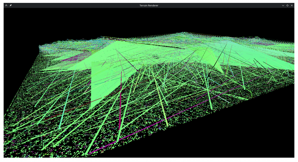
Now I could increase the sampling ratio and look at the smooth curves. But when I did I did not see what I expected.
I thought this was aliasing between sampling rate and control point rate. To combat it, I opened wikipedia and copied myself a nice list of prime numbers that I could use instead of normal fractions. This did not help at all. In the process of debugging this I realized my control point matrix was wrong and fixed it, and realized the B-Spline matrix lacked the 1/6 normalization term but left it out as with it my geometry was very short. While trying to render much simpler B-Spline surfaces I also realized that the dted data I was displaying was not supposed to be a thin rectangle as I thought.
In the process of debugging I added a flat shaded display mode, toggled by ‘f‘.
After debugging for a long time, I discovered that my s and t variables were integers 🤦♀️. However, when I turned s and t into floats I realized that the mishapen plane was the least of my problems.
Whatever this was, it was the opposite of aliasing as it was less severe when the sampling ratio was an integer multiple or divisor. After even more debugging, I came to the realization that glm processed matricies in a column first order. This meant my basis and control point matricies have been wrong all this time. After transposing them and adding the 1/6 term the rendering seemed to be sane again. But an old friend was back:
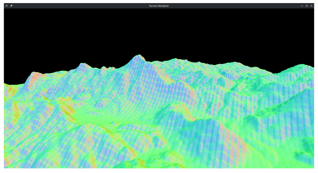
I remembered that with the transposed inner matrix, S and T also needed to be switched. This seemed to prevent aliasing, at least initially. But when I increased the tesselation ratio it was still there:
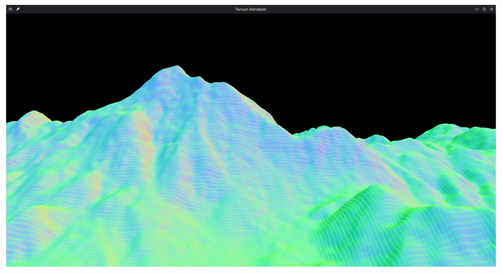
After another long debugging session, I found that at some point during debugging I had changed a value in the basis matrix and it was wrong. Finally after fixing that as well, the tesselation seemed to work fine.
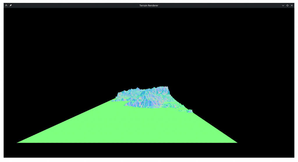
I spent an embarrasingly long time trying to figure out why only a third of the map was visible. I had passed faceCount directly to indexCount thinking OpenGL wanted the number of primitives, and fixing that as well, I had a nice square map.
Shading
I added the toggle for wireframe mode and the only thing remaining was shading. In the fragment shader I added diffuse lighting based on direction and baseline world lighting that are summed and multiply color values received from the fragment shader. I wanted specular highlights so I made a web search and found something about raising the directional light to some power but it didn’t do much. In hindsight that’s because the normals are always smaller than 1 so when I took the larger of 1 or the specular it always returned 1. Since then I tried fixing it but it looks like plastic with it on so I don’t regret botching it.
For the colors I began by implementing 4 layered colors as required, but I quickly abondoned it as it didn’t look very nice.
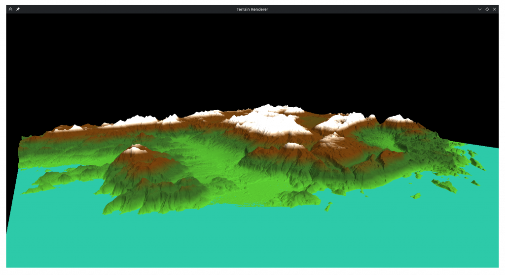
Instead I incorporated the surface normals into the calculation to decide which areas would be brown or white, which produced a more pleasing image:
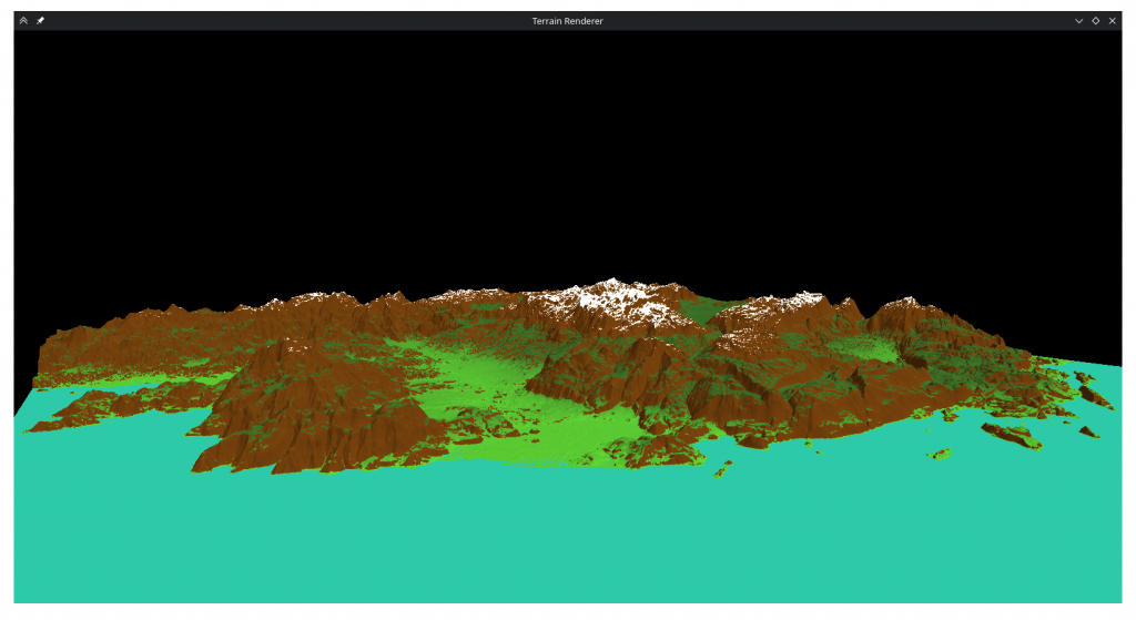
I know this wasn’t what was specified, but as ‘artistic discretion’ was metioned I thought what looked better to me would be better to include.
Finally I added normalization to movement direction and fixed a bug where if movement buttons for opposite irections were pressed at the same time it would result in a 0 vector and launch the camera to nan.
Conclusion
This was a nice and fun homework. It is quite satisfying to write code and see the results of it visibly on the screen. I had difficulties with some parts but I think it all worked out at the end. I hope the code I wrote is condusive to adapting for the second homework.
Epilogue
With prime sampling rates I couldn’t notice aliasing, but I’ve been wondering what would happen if I use just any sampling ratio. So I tried between 1 and 2 in 0.01 increments and…
Similar artifacting happens at 1.07, 1.08, 1.19, 1.20, 1.32, 1.44 and 1.45 ratios. I have iterated over the entire spline array to see if the corners line up with each other and discovered that they don’t, they deviate on the order of 1e-4. I had run a similar iteration over a simpler mesh after the last time I fixed aliasing and it didn’t show discontinuities so I don’t know why it is now misbehaving on the actual mesh. My best guess would be that since the height data is on the order of 1e3 and floats have an accuracy of 1.5e-7 the fine detail is getting lost. However the aliasing doesn’t only happen in mountaintops and there are many neighbors that have deviancy / height ratios over 1e-6 so I’m not very confident that this is indeed the case.
Revisions
Reading this with fresh eyes, it’s possible I misremembered the order of events of the alisaing debugging, as the way I wrote it here doesn’t make sense. If everything was transposed and multiplied in the wrong order, that should’ve been the same as them not being transposed and multiplied in the right order. What possibly happened is that before converting t and s to floats I unfixed the control point matrix and caused the spiky terrain. Then I fixed the control point matrix and transposed it at the same time, but thought transposing was what fixed it.